LmrXP142机械手册.pdf - 第113页
AC Servopack Check List for Troubleshooting Alarm title Alarm Cause Investigation and corrective actions NP1MT011Ea E1H EEPROM abnormality Correct value not read by CPU by nonvolatile memory of built-in servo amplifier. …
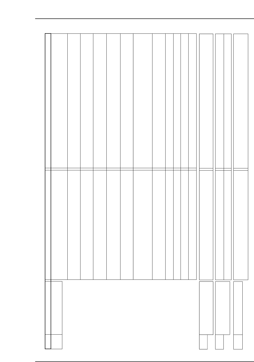
AC Servopack Check List for Troubleshooting
Alarm titleAlarm Cause Investigation and corrective actions
NP1MT007E-2a
D1H Excessive position deviation Position command frequency is high or acceleration and
declaration time is short.
Correct the position command of the controller.
Excessive initial load or low motor capacity. Correct the load condition or increase the motor capacity.
Holding brake is not released. Check the wiring and repair any abnormalities. If specified voltage is
applied, replace the servo motor.
Motor is mechanically locked or machine is colliding. Check the machinery system.
Settings of servo parameters (Position loop gain,etc.)
are not appropriate.
Check the servo parameter settings (raise the position loop gain, etc.)
Excessive deviation setting value is reduced. Set a greater value for excessive deviation.
Defect in control panel of servo amplifier. Replace the servo amplifier.
Servo motor encoder is defective. Replace the servo motor.
Power supply voltage is low. Check the power supply voltage.
One or all phases of U/V/W -phase of the servo amplifier
and motor has disconnected.
Check and repair the wiring connections.
Motor is being rotated by an external force (Gravity, etc.)
during stopping (positioning completion).
Check the load, and/or increase the motor capacity.
• Valid current limit command is entered by the
controller, and the current limit setting is reduced.
•
Number of encoder pulses does not match with the motor.
Increase the current limit value or disable the current limit. Match the
number of motor encoder pulses.
D2H Position pulse frequency
abnormality 1
Command for the digital filter setting of the command
pulse input is entered.
• Decrease the frequency of the command pulse.
• Increase the frequency of the digital filter.
D3H Abnormal position pulse
frequency 2
Frequency of command pulse input is excessive. Reduce the frequency of command pulse input.
Setting value of electronic gear is excessive. Decrease the electronic gear setting value.
DFH Test mode end Normal operation Clear the alarm and restore operation. (After completion of test mode,
to confirm any deviation in the controller).
Part 5 Chapter 1 Servo System Troubleshooting
Edition 3.0 5-1-13 XP-142E Mechanical Reference
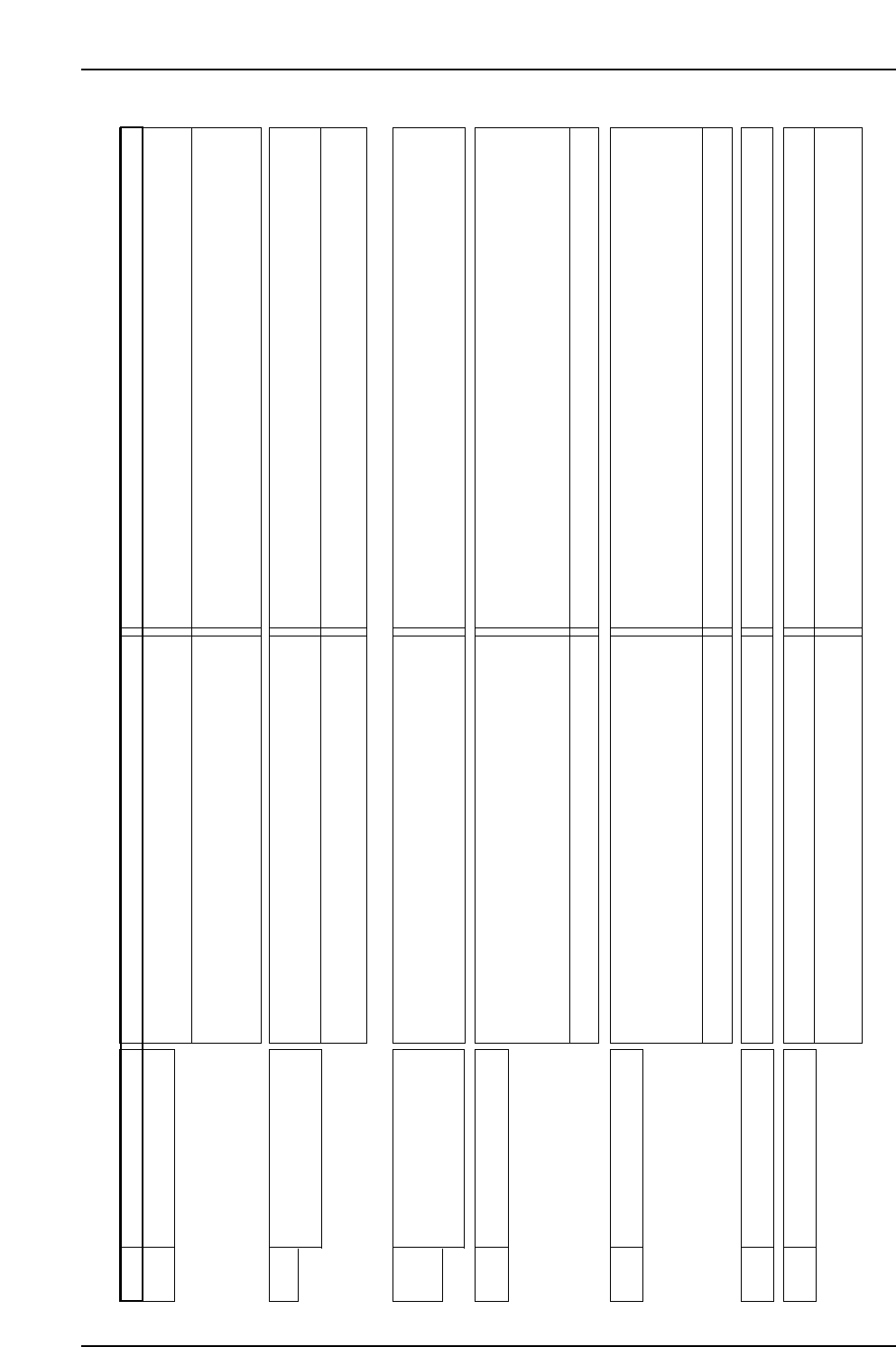
AC Servopack Check List for Troubleshooting
Alarm titleAlarm Cause Investigation and corrective actions
NP1MT011Ea
E1H EEPROM abnormality Correct value not read by CPU by nonvolatile memory
of built-in servo amplifier.
Replace the servo amplifier.
Failed to write into the nonvolatile memory during last
power supply cutoff.
• Change the optional parameters, turn ON the power supply again,
and confirm that alarm has cleared.
→ If alarm is not cleared, replace the servo amplifier.
E5H Parameter error 1 Selected value is outside the specified range of a system
parameter.
• Confirm the model number of the servo amplifier.
• Confirm selected values of system parameters and modify if
necessary.
→ Turn ON the power again and confirm that alarm is cleared.
Defect in servo amplifier Replace the servo amplifier.
E6H Parameter error 2 Selected values of system parameters and actual
hardware do not match. Improper assembly of system
parameter settings.
• Confirm the model number of servo amplifier.
• Confirm selected values of system parameters and correct if
necessary.
→ Turn ON the power again and confirm that alarm is cleared.
Defect in servo amplifier Replace the servo amplifier.
Defect in servo amplifier control panel. Replace the servo amplifier.
Malfunction due to noise • Confirm proper grounding of the amplifier.
• Add ferrite core or similar countermeasures against noise.
E2H
EEPROM internal data
abnormality
Correct value not read by CPU by nonvolatile memory
of built-in servo amplifier.
Replace the servo amplifier.
F2H Initial time out Defect in internal circuit of servo amplifier. Replace the servo amplifier.
F1H Abnormality in task process Abnormality in control circuit of servo amplifier Replace the servo amplifier.
E3H
E4H
Internal RAM abnormality
Abnormality in process
between CPU and ASIC
Defect in the servo amplifier control panel. Replace the servo amplifier.
Part 5 Chapter 1 Servo System Troubleshooting
Edition 3.0 5-1-14 XP-142E Mechanical Reference
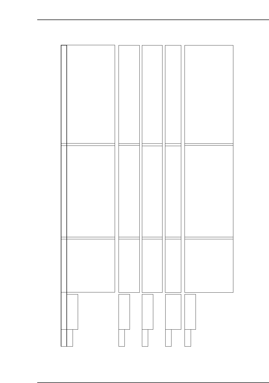
AC Servopack Check List for Troubleshooting
Alarm Alarm Name Status Cause Remedy
A.020 Parameter
Checksum Error
• Occurred when the
control power supply was
turned ON.
• The control power supply ranged from 30
VAC to 60 VAC.
• The power supply was turned OFF while
changing the parameter setting.
• The number of times that parameters were
written exceeded the limit. For example, the
parameter was changed every scan through
the host controller.
• The SERVOPACK EEPROM and the related
circuit are faulty.
• Correct the power supply, and set Fn005 to
initialize the parameter.
• Set Fn005 to initialize the parameter and input
the parameter again.
• Replace the SERVOPACK.
• Replace the SERVOPACK.
A.030 Main Circuit
Detector Error
• Occurred when the
control power supply was
turned ON or during
operation
• A SERVOPACK fault occurred. • Replace the SERVOPACK.
A.050 Combination
Error
• Occurred when the
control power supply was
turned ON.
• The SERVOPACK and servomotor capacities
do not correspond to each other.
Servomotor capacity / SERVOPACK capacity
≤ 1/4
or
servomotor capacity / SERVOPACK capacity
≥ 4
• The parameter that is written in the encoder
is incorrect.
• A SERVOPACK board fault occurred.
• Select the proper combination of SERVOPACK
and servomotor capacities.
• Replace the servomotor (encoder).
• Replace the SERVOPACK.
A.040 Parameter
Setting Error
• Occurred when the
control power supply was
turned ON.
• The SERVOPACK and servomotor capacities
do not match each other.
• The SERVOPACK EEPROM and the related
circuit are faulty.
• Select the proper combination of SERVOPACK
and servomotor capacities.
• Replace the SERVOPACK.
A.041 Dividing Pulse
Output Setting
Error
• Occurred when the
control power supply was
tuned ON.
• The PC dividing pulse set for Pn212 is out of
the setting range and does not satisfy the
setting conditions.
• Set Pn212 to the correct value.
NP1MT012E
Part 5 Chapter 1 Servo System Troubleshooting
Edition 3.0 5-1-15 XP-142E Mechanical Reference
<For Y-, G-, F-, R-, Q-, Z-axis (
ΣΣ
III servo amplifier)>