LmrXP142机械手册.pdf - 第134页
Wiring the T ransformer 1. Remove the transformer box cover. 2. Wire the primary taps to match the supplied voltage. Transformer box XP1MS205E Part 6 Chapter 3 Electrical Power Supply & Transformer W iring Edition 3.…
Part 6 Chapter 3 Electrical Power Supply & Transformer Wiring
Edition 3.0 6-3-1 XP-142E Mechanical Reference
3. Electric Power Supply & Transformer Wiring
Point
Wire the transformer inside the machine so that its voltage matches the supplied voltage.
Power consumption is 4.0 kVA. Ensure that the power supply is equal to or greater than
4.0 kVA.
Procedure
DANGER
Make sure that the external power supply is switched off
before attempting this procedure.
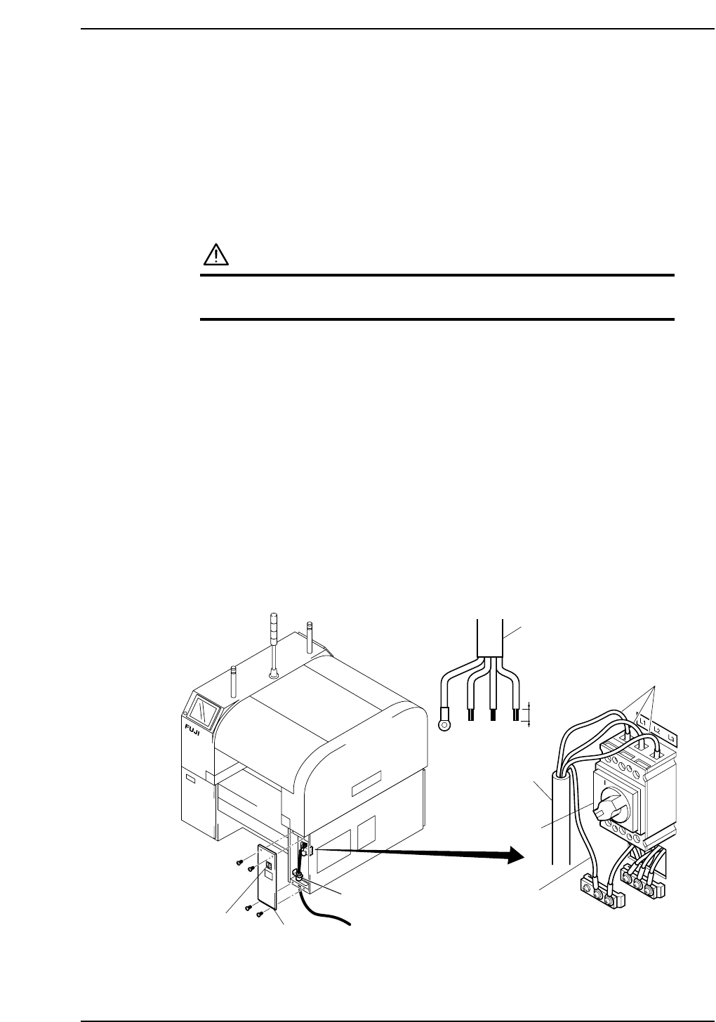
Connecting the Power Supply
1. Detatch the MFU from front side (side 1) of the machine.
2. Turn the breaker switch off. Loosen the cover mounting screws (four) and remove
the cover.
3. Pass the power cable through the cable inlet under the machine to the main switch.
4. Connect the ground wire to the ground terminal.
5. Connect the three-phase wires to the main switch, using the specified screw
tightening torque.
Terminal screw tightening torque: 5.8 N·m
Note: After disconnecting the power supply and confirming that it is off, check the screw
torque periodically.
6. After connecting the wires, fasten them with the cable lock nut.
Cable lock nut tightening torque: 7.5 N·m
14 mm
Ground
Breaker
switch
Cover
Power cable
Power cable
Main breaker
XP1MS204aE
Recommended driver: Blade 8 X150 mm
Cable clamp
3-phase wire
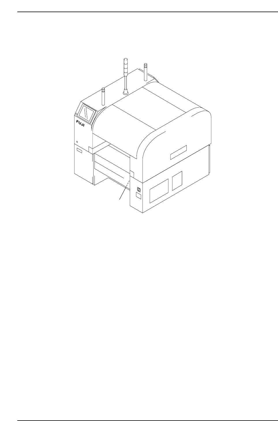
Wiring the Transformer
1. Remove the transformer box cover.
2. Wire the primary taps to match the supplied voltage.
Transformer box
XP1MS205E
Part 6 Chapter 3 Electrical Power Supply & Transformer Wiring
Edition 3.0 6-3-2 XP-142E Mechanical Reference
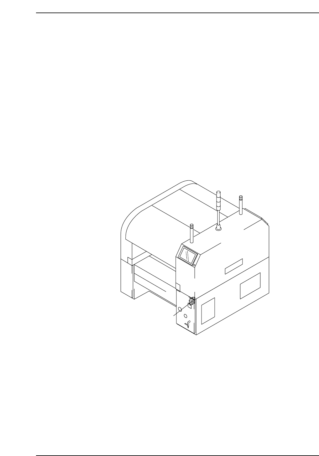
4. Connecting the Data Transmission Cable
<RS-232C>
Point
The machine is connected to the host computer by means of an RS-232C communication
cable, which permits program transmissions and production log collection.
Procedure
1. Register the machine in the line descriptor file at the host.
Note: Refer to the host computer manual for details regarding the registration procedure.
2. Connect one end of the transmission cable to the designated port at the host, and
connect the other end to the connector on the machine.
Note: Shielded cables are recommended if cable types other than Ethernet are used.
Data cable port
XP1MS206E
Part 6 Chapter 4 Connecting the Data Transmission Cable <RS-232C>
Edition 3.0 6-4-1 XP-142E Mechanical Reference