LmrXP142机械手册.pdf - 第84页
Part 4 Adjustments 1. Servo Amplifier Adjustments . . . . . . . . . . .4-1-1 This section explains adjustments that can be performed by the user .
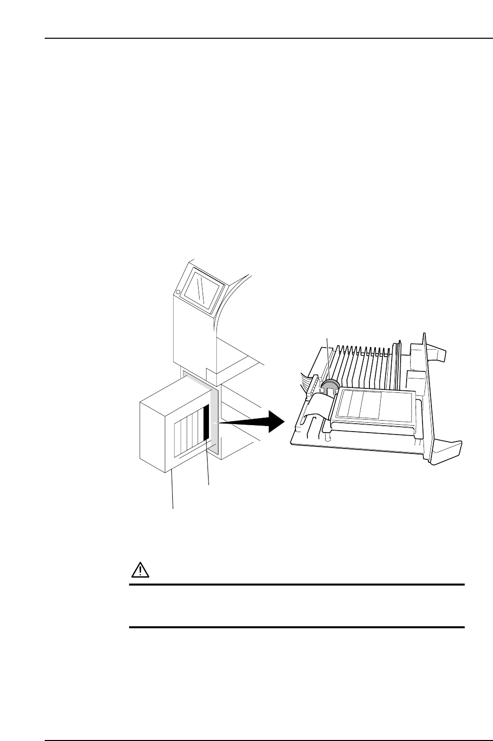
3.6 Replacing the CPU Board Battery
Point
If the SRAM (memory) backup battery on the CPU board fails, then problems such as
lack of trace data will occur. Replace this battery regularly, at 6 year intervals.
Procedure
1. Turn off the power to the machine at the main switch (breaker).
2. Remove the CPU board from the Control Box.
3. Replace the lithium battery (CR2450, commercially available) on the CPU board.
4. Return the CPU to the Control Box.
5. Turn on the machine power and follow the instructions that appear on screen to
resume operation.
CAUTION
• Do not use any battery other than the specified battery.
• Dispose of the used lithium battery in accordance with
your local regulations.
Lithium battery
Control box
CPU board
XP1MA036E
Part 3 Chapter 3 Replacing Consumable Parts
Edition 3.1 3-3-8 XP-142E Mechanical Reference

Part 4
Adjustments
1. Servo Amplifier Adjustments . . . . . . . . . . .4-1-1
This section explains adjustments
that can be performed by the user.
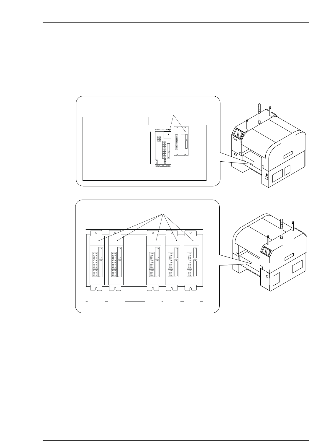
1. Servo Amplifier Adjustments
1.1 Servo Amplifier Parameters
1. Check the servo amplifier parameters using the panel operator controls on the face
of the amplifier. Digital operator JUSP-OP05A can also be used to check the Y, G,
F, R, Q, and Z servo amplifier parameters.
XP1MA007aE
Front (Side 1)
Rear (Side 2)
Servo box 1
LED display
X-axis
Y-axis
Servo box 2
LED display
G-axis F-axis R-axis Q-axis Z-axis
Part 4 Chapter 1 Servo Amplifier Adjustments
Edition 3.0 4-1-1 XP-142E Mechanical Reference