LmrXP142机械手册.pdf - 第37页
V ision System Parts Camera The parts camera is used to identify the shape and size of parts which have been picked up by the nozzles. The machine is equipped with a single CCD camera. Lighting A frontlight system is use…
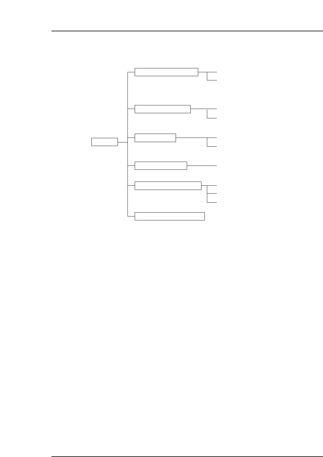
2. Functions of Each Component
*: Either the MFU-X10E or the fixed device table can be selected at the time of shipment as
an optional item. The machine can be equipped with one of these optional units.
Parts Mounting System
XY-robot
The XY-robot is equipped with a placing head which moves in the X and Y directions.
Placing head
The placing head is equipped with a mark camera and a multiple nozzle holder.
Independent Q-axis, Z-axis, and R-axis servo motor control is performed for nozzles
mounted in the nozzle holder.
Parts Supply System
Fixed device table
This unit can load 50 tape feeders (8 mm tape width conversion) at maximum.
MFU-X10E (Multifeeder Unit)
The MFU-X10E holds the tape feeders, and is attached at the removable supply side of
the machine (rear).
XP-142E
XP1MN206E
Parts mounting system XY-robot
Placing head
MFU-X10E*
Parts camera
Mark camera
Conveyor
Control panel
Control box
Servo box
Fixed device table*
Parts supply system
Vision system
Panel conveyance
Electrical control system
Pneumatic control system
Part 1 Chapter 2 Functions of Each Component
Edition 3.0 1-2-1 XP-142E Mechanical Reference
Vision System
Parts Camera
The parts camera is used to identify the shape and size of parts which have been picked
up by the nozzles. The machine is equipped with a single CCD camera.
Lighting
A frontlight system is used, featuring a strobe light.
Mark camera
This camera reads the fiducial marks on panels being produced so that the coordinates
can be corrected.
Panel Conveyance
Conveyor
The conveyor loads panels from the previous machine, and unloads panels to the next
machine following production.
Electrical Control System
Control Panel
The control panel is equipped with the buttons and touch-screen functions used to
operate the machine.
Control Box
The control box contains the boards and circuitry required to control the machine, as
well as the 3.5-inch floppy drive and hard drive storage devices.
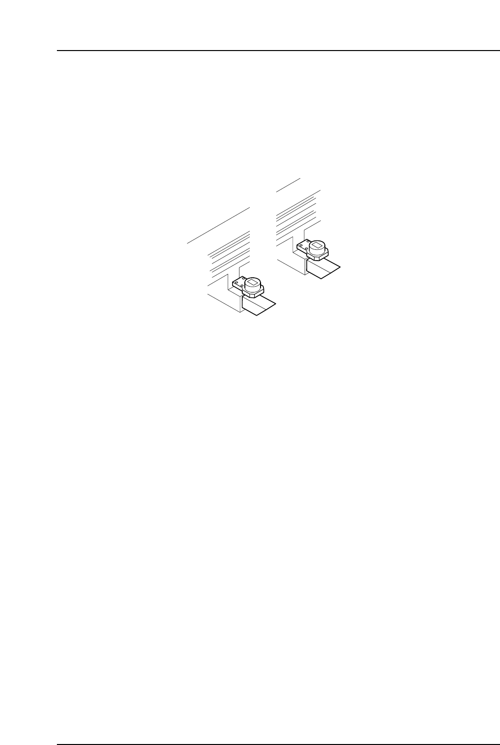
Servo Boxes 1 and 2
Servo box 1 is located on Side 1, inside the door beneath the waste tape cutter. Servo box
2 is located on Side 2, inside the door beneath the waste tape cutter.
Note: Except for servo amplifier battery replacement, refrain from performing any maintenance
operations inside these boxes.
Side 1
Side 2
XP1MN207
Part 1 Chapter 2 Functions of Each Component
Edition 3.0 1-2-2 XP-142E Mechanical Reference

Part 2
Basic Operation
1. Changing the Conveyor Width . . . . . . . . .2-1-1
2. Changing the Position of the Back-up Pins
. . . . . . . . . . . . . . . . . . . . . . . . . . . . . . . . .2-2-1
3. Using the Maintenance Key . . . . . . . . . . . .2-3-1
This section explains the basic
machine operation procedures.