LmrXP142机械手册.pdf - 第78页
3.2 Replacing the Conveyor Belt Procedure W ARNING Cut power to the machine at the main switch before attempting this procedure. 1. Loosen the set screws on the pulley rod, and slide the rod in the direction of the arrow…
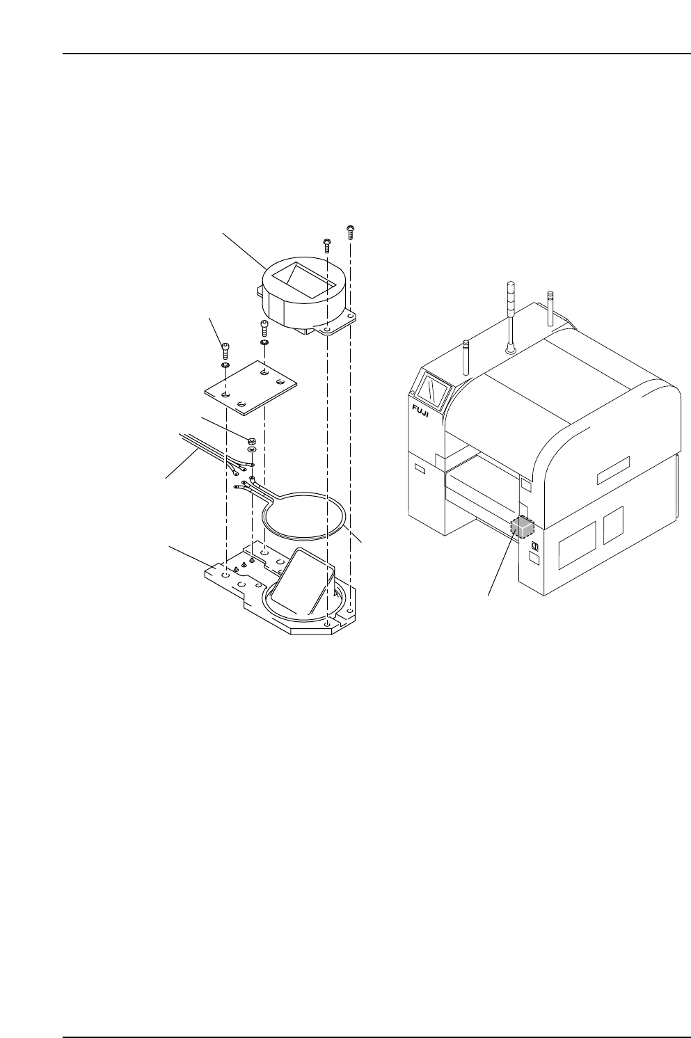
1. Remove the lock screws (four) shown below, then remove the light cover.
2. Loosen the nuts (three), then replace the strobe light.
Note: When mounting the strobe light, avoid touching the strobe light glass with your
hands. Oil from hands can shorten the life of the strobe light.
Strobe power unit
XP1MR201Ea
Nut
Holder
Lock screw
Strobe light
Light cover
Harness
Part 3 Chapter 3 Replacing Consumable Parts
Edition 3.1 3-3-2 XP-142E Mechanical Reference
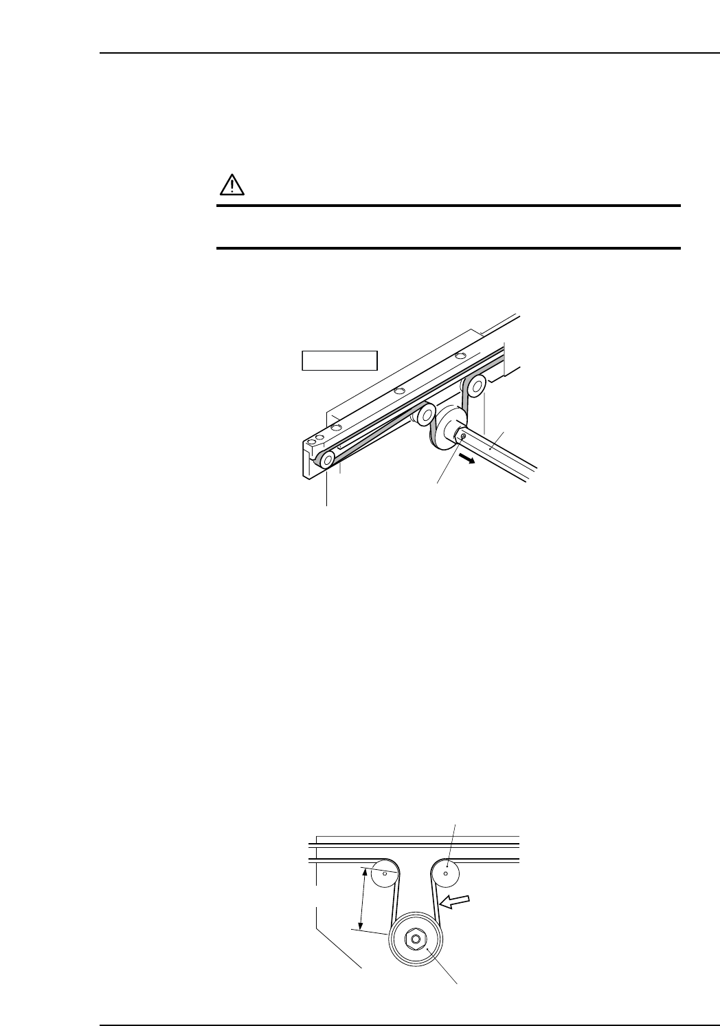
3.2 Replacing the Conveyor Belt
Procedure
WARNING
Cut power to the machine at the main switch before
attempting this procedure.
1. Loosen the set screws on the pulley rod, and slide the rod in the direction of the
arrow.
2. Loosen the belt tension pulley.
3. Remove the In-Station and Main-Station side plates.
4. Removal of the conveyor top plate is not necessary. At the end of the conveyor,
pull a small section (about 5 mm) of the conveyor belt off of the guide.
5. Manually pull the conveyor belt in the reverse direction to remove the conveyor
belt. The derailed section of the belt will slide to the opposite end of the conveyor.
6. Use the reverse procedure to install the new belt. Engage a small section of the belt
and pull the belt so that the engaged section slides to the opposite end.
7. Return the pulley rod and tighten its set screws.
8. Tighten the tension pulley bolt, using a tension meter (Hz) to adjust the tension as
shown below.
9. Return the In-Station and Main-Station side plates.
Conveyor belt tension tolerance (frequency): 425 ~ 445 Hz
Measurement position: Midway between the conveyor belt drive pulley and the
tension pulley (approximately 50 mm).
Tension pulley tightening torque: 3.0 N·m
Tension pulley
Approx. 50 mm
Belt tension
measuring position
Drive pulley
XP1MR204E
XP1MR202E
Fixed rail
Set screw
Rod
Part 3 Chapter 3 Replacing Consumable Parts
Edition 3.1 3-3-3 XP-142E Mechanical Reference
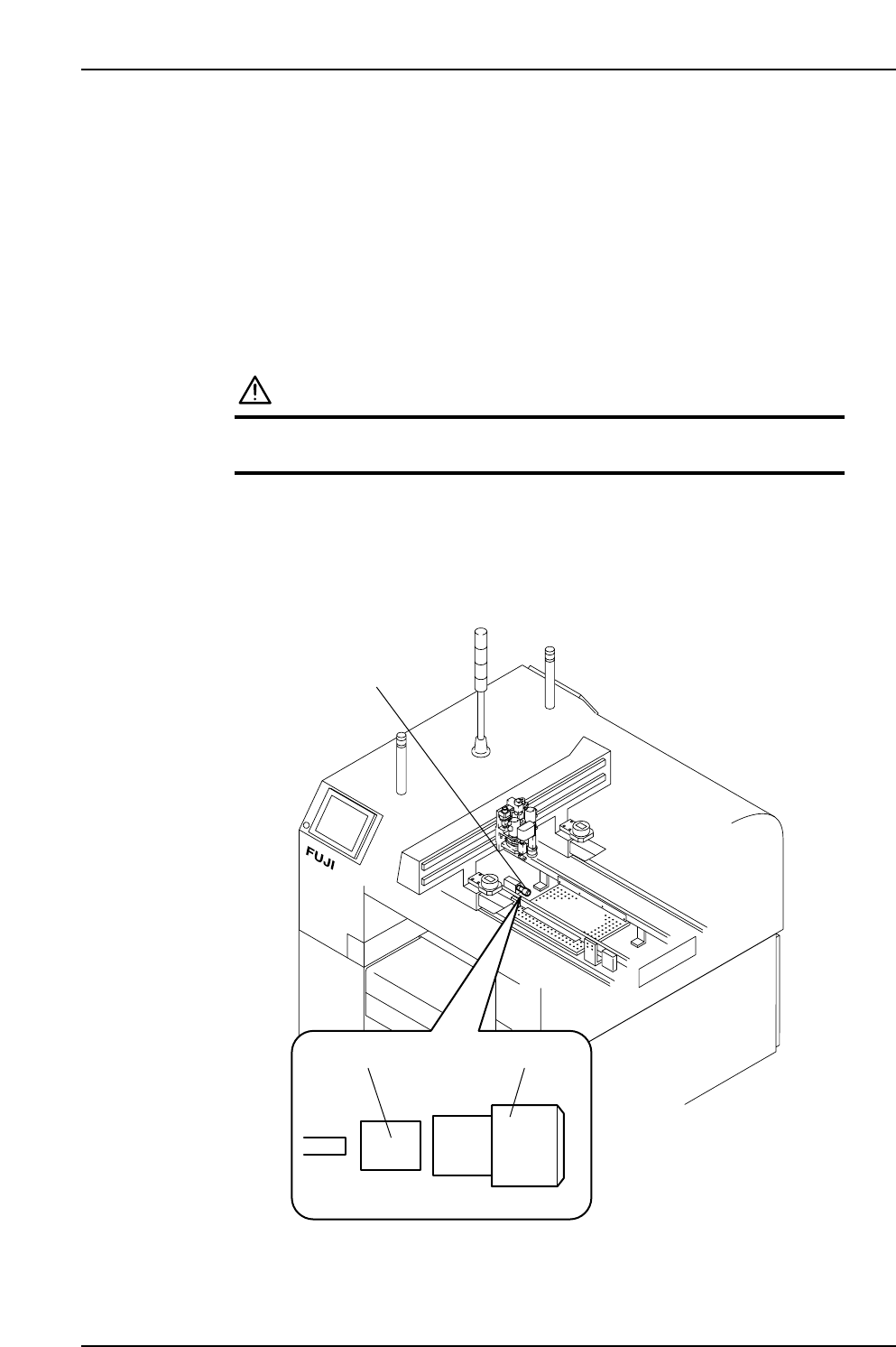
3.3 Replacing the Filter of the Vacuum Generator
Used for Gauge Chip Part Pick-up (Every Year)
Point
The vacuum generator used for gauge chip part pick-up is equipped with a dust filter.
This filter should be replaced regularly to ensure stable part holding.
Procedure
WARNING
Cut power to the machine at the main switch before
attempting this procedure.
1. Turn the filter counterclockwise to remove.
2. Replace the old filter element with a new one.
XP1MR205E
Filter element
Filter of vacuum generator
used for gauge chip
part pick-up
Filter case
Part 3 Chapter 3 Replacing Consumable Parts
Edition 3.1 3-3-4 XP-142E Mechanical Reference