LmrXP142机械手册.pdf - 第99页
Part 5 T roubleshooting 1. Servo System T roubleshooting . . . . . . . . .5-1-1 This section explains basic procedures for troubleshooting the machine and its peripheral devices. Use this section as a reference for ident…
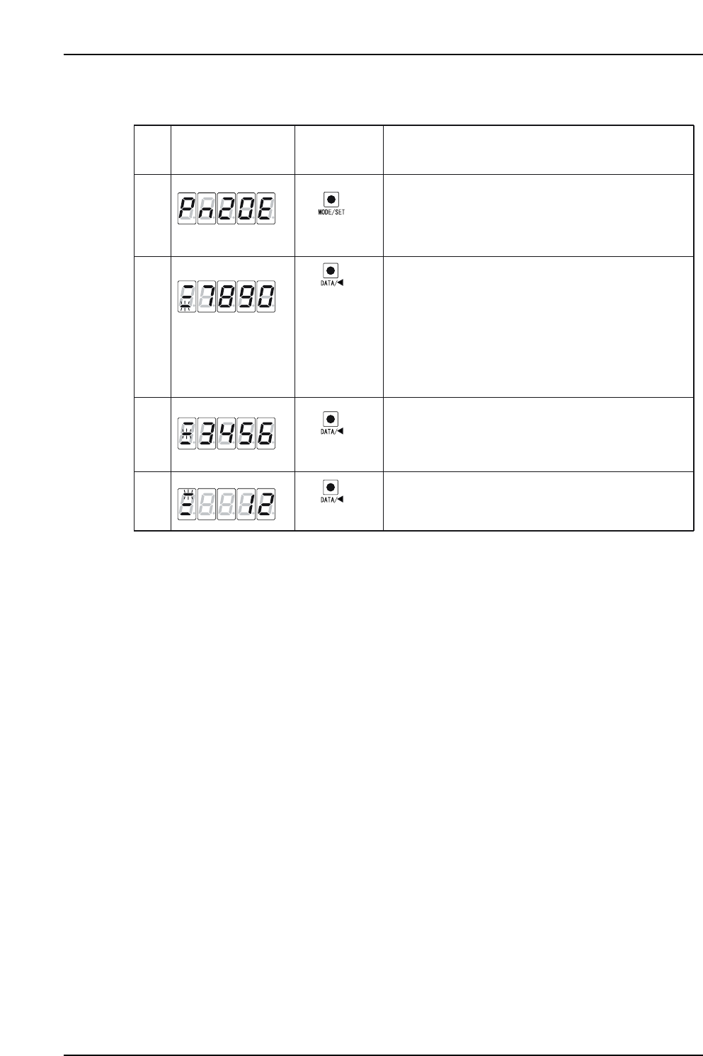
3. Procedures for display and setting of [Pn20E = 1234567890] are shown below.
Push the MODE/SET key to select the parameter setting
mode. If Pn20E is not displayed, then select Pn20E
by pushing the UP or DOWN keys.
*The digits that can be operated will blink.
XP1MA034E
(DATA/SHIFT)
(1 sec. or more)
Bottom 4 digits
Middle 4 digits
(MODE/SET key)
Display after
Operation
Description
Panel
Operator
1
2
4
Push the DATA/SHIFT key for at least one second.
The current Pn20E data is displayed.
The bottom 4 digits are displayed first, and the
rightmost digit will blink when selected.
Push the DATA/SHIFT key to move to other digits,
and change a digit's value by pushing the UP/DOWN keys.
When DATA/SHIFT is pushed while the 4th digit (7) is
selected, the middle 4 digits are displayed and the
5th value (6) blinks.
If DATA/SHIFT is pressed while the 10th value (1) is
selected, the bottom 4 digits are displayed again. In this
way, the selection can be moved one digit to the left.
(DATA/SHIFT)
(DATA/SHIFT)
3
In the same way, when DATA/SHIFT is pushed the select-
ed value moves from the 5th to the 8th digit
When DATA/SHIFT is pressed when on the 8th digit (3),
the top 2 digits are displayed and the 9th (2) is selected.
Top 2 digits
Part 4 Chapter 1 Servo Amplifier Adjustments
Edition 3.0 4-1-14 XP-142E Mechanical Reference

Part 5
Troubleshooting
1. Servo System Troubleshooting . . . . . . . . .5-1-1
This section explains basic procedures for
troubleshooting the machine and its
peripheral devices. Use this section as a
reference for identifying and resolving
minor problems to restore the machine to its
proper condition.
Contact a Fuji agent for serious problems or
repairs that cannot be performed.
Part 5 Chapter 1 Servo System Troubleshooting
Edition 3.0 5-1-1 XP-142E Mechanical Reference
1. Servo System Troubleshooting
An AC servo system controls all servo axes in the machine. If there is a problem with the servo
system, the machine displays an alarm code to notify the operator.
This section describes alarm codes and inspection methods, and should be used as a reference for
troubleshooting and resolving problems.
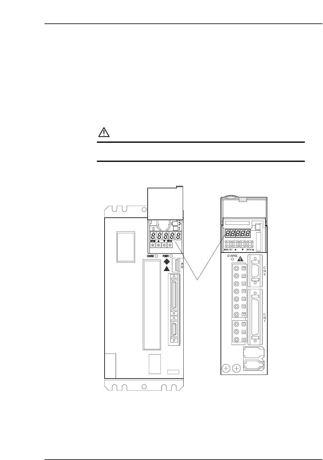
1.1 Alarm Code Display
Each servo amplifier has an LED panel to display alarm codes.
The following illustrations show the location of each servo amplifier’s LED panel.
DANGER
The servo amplifier power terminal is high voltage.
Do not touch the servo amplifier power terminal.
Note: For the Y, G, F, R, Q, and Z-axes, to display the alarm code on the digital operator, connect
the digital operator (JUSP-OP05A) to the servo amplifier CN3 connector.
XP1MA035E
X-axis
Y, G, F, R, Q,
and Z-axes
LED panel