LmrXP142机械手册.pdf - 第104页
AC Servopack Check List for Troubleshooting Alarm title Alarm Cause Investigation and corrective actions NP1MT001Eb-2 41H Electrical overload 1 Defect in servo amplifier control panel or power element peripheral Replace …
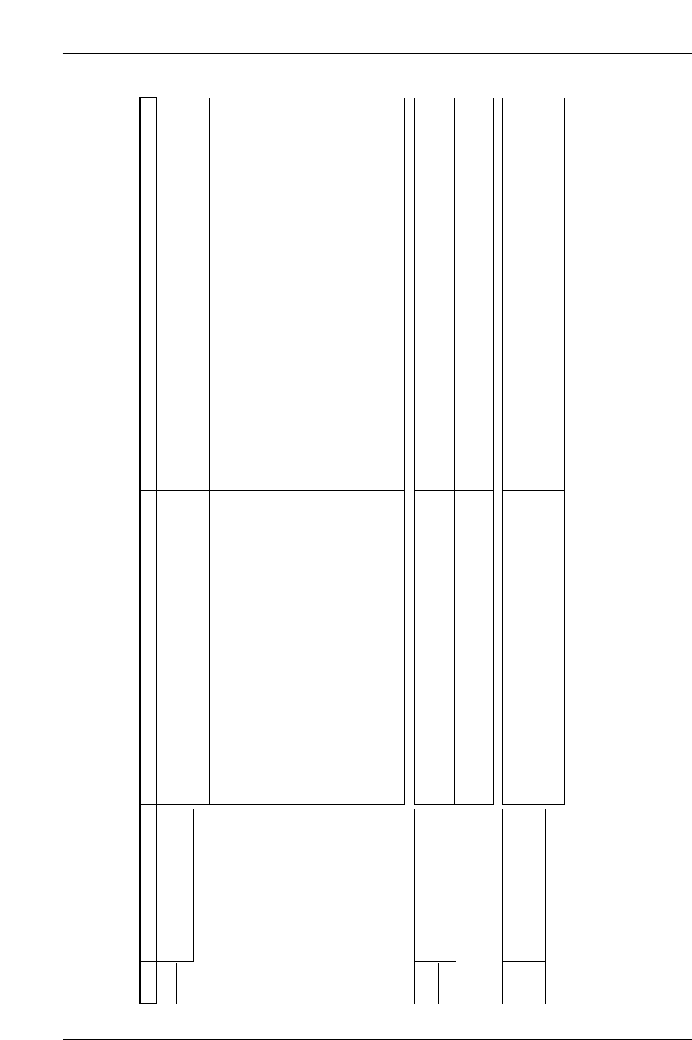
AC Servopack Check List for Troubleshooting
Alarm Alarm title Cause Investigation and corrective actions
21H Power device Abnormality
(Over current)
U/V/W-phases of amplifier is short circuited due to the
wiring in amplifier and motor. Also, U/V/W-phases are
grounded in the earth.
Check the wiring between the amplifier and motor, and confirm that
there is no error. If some error is detected, modify or change the
wiring.
Short circuit or fault in U/V/W-phases on servo motor
side.
Replace the servo motor.
• Defect in control print panel
• Defect in power device
Replace the servo amplifier.
Overheat is detected in Power device (IPM). • Confirm that the cooling fan motor for the servo amplifier is working.
If it is not working, replace the servo amplifier.
• Confirm that that the temperature of the control panel (ambient
temperature of the servo amplifier) does not exceed 55 degrees.
If in excess of 55 degrees, check the installation method of the
servo amplifier, and confirm that the cooling temperature of the
control panel is set to below 55 degrees.
22H
Electric current abnormality 0
• Defect in control print panel
• Defect in power device
Replace the servo motor.
Servo amplifier and motor are not combined properly. Confirm that the proper codes (per the specified Motor Codes) have
been used for the servo motor; if not, replace the servo motor.
23H
24H
Electric current abnormality 1
Electric current abnormality 2
Defect in internal circuit of servo amplifier Replace the servo amplifier
Malfunction due to noise Confirm proper grounding of the amplifier Add ferrite core or similar
countermeasures against noise.
NP1MT001Eb-1
Part 5 Chapter 1 Servo System Troubleshooting
Edition 3.0 5-1-4 XP-142E Mechanical Reference
<For X axis (Q series servo amplifier)>
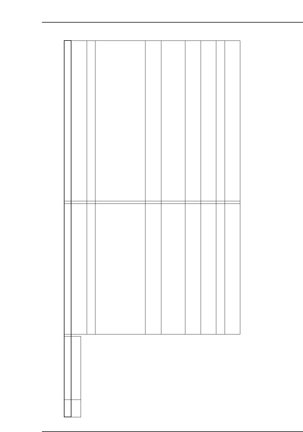
AC Servopack Check List for Troubleshooting
Alarm titleAlarm Cause Investigation and corrective actions
NP1MT001Eb-2
41H Electrical overload 1 Defect in servo amplifier control panel or power element
peripheral
Replace the servo amplifier.
Defect in encoder circuit of servomotor. Replace the servo motor.
Effective torque exceeds the rated torque. • Monitor the motor-generated torque in the effective torque
estimated value (Trms), and confirm that the effective torque
exceeds the rated torque.
• (Or,) calculate the effective torque of the motor from its loading and
operating conditions
→ If the effective torque is excessive, check the operating or loading,
or replace the capacity of the large motor.
Defect in motor-amplifier combination. Check if the motor in use matches with the recommended type, and
replace if it is improper.
Holding brake of servo motor does not release. Check that the wiring and voltage of the holding brake are acceptable;
if not, repair.
→ If the above are OK, replace the servomotor.
Wiring of U/V/W-phase between servo amplifier and
motor do not match.
Check the wiring conditions and restore if improper.
One or all connections of U/V/W-phase wiring of servo
amplifier / motor is disconnected.
Check the wiring conditions and restore if improper.
Machines collided. Check the operating conditions and limit switch.
Encoder pulse number setting does not match with the
motor.
Match the encoder pulse number with the motor.
Part 5 Chapter 1 Servo System Troubleshooting
Edition 3.0 5-1-5 XP-142E Mechanical Reference
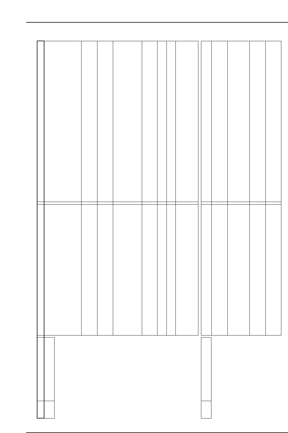
AC Servopack Check List for Troubleshooting
Alarm titleAlarm Cause Investigation and corrective actions
NP1MT002Ea
43H Regeneration abnormality • Exceeded permitted value of regenerating power in
built-in regenerative resistance specifications.
• Excessive load inertia, or tact time is short.
• Check the load inertia and operating pattern.
• Use an external regeneration resistor.
• Set the load inertia within the specified range.
• Increase the deceleration time.
• EIncrease the tact time.
Regenerative resistance wiring conflicts with built-in
regenerative resistance specifications.
Check wiring and replace if incorrect.
Regenerative resistance wiring conflicts with external
regeneration resistor specifications.
Check wiring and replace if incorrect.
Regeneration resistor is disconnected. • For built-in regeneration resistor specifications, replace the servo
amplifier.
• For external regeneration resistor specifications, replace the
regeneration resistor.
Resistance value of external regeneration resistor is
excessive.
Replace the current resistance value with a value matching the
specifications.
Input power supply voltage exceeds the specified range. Check the input power supply voltage level.
Defect in control circuit of servo amplifier. Replace the servo amplifier.
When external regenerative resistance is selected for
system parameter Page OE and external regenerative
resistance is not installed.
• Install the external regenerative resistance.
• Set to "Do not connect regenerative resistance".
51H Amplifier overheating Defect in internal circuit of servo amplifier. Replace the servo amplifier.
Regenerating power exceeded. • Check the operating conditions.
• Use external regeneration resistor.
Regenerating power is within the specified range but
ambient temperature of servo amplifier is out of specified
range.
Confirm that the cooling method maintains the temperature of control
panel between 0 to 55 degrees.
Regenerating power is within the specified range but
built-in cooling fan of servo amplifier is stopped.
For an amplifier equipped with a fan motor, check that the fan motor
is running; if not, replace the servo amplifier.
Regeneration energy during emergency stop exceeded. • Change the servo amp.
• Check the loading condition.
Part 5 Chapter 1 Servo System Troubleshooting
Edition 3.0 5-1-6 XP-142E Mechanical Reference