LmrXP142机械手册.pdf - 第93页
Basic mode selection and operation procedure Alarm traceback display and Parameter check are two of the basic modes. Change the basic mode at the panel operator to check operation status, parameters, or alarm traceback d…
1.1.2 Y, Z, Q, R, F and G-axes Servo Amplifier (Sigma-III Series)
Parameter Check
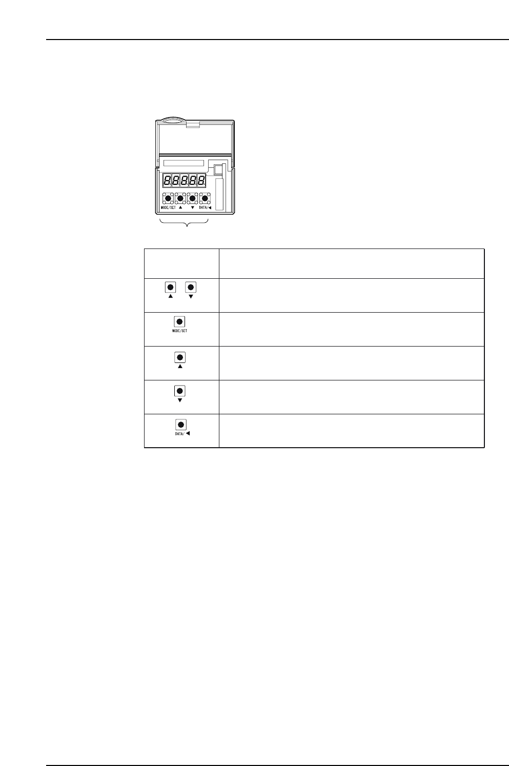
The keys and functions are explained below.
XP1MA027E
Panel operator
+
(Push together)
(DOWN)
(DATA/SHIFT)
(UP)
(MODE/SET)
Push both buttons together to reset the servo alarm.
Keys on
Panel Operator
Function
Push to change a basic mode (status display mode, utility function
mode, parameter setting mode, or monitor mode).
Push the UP key to increase the set value. For JOG operation, this
key is used as a Forward Run Start Key.
Push the DOWN key to decrease the set value. For JOG operation,
this key is used as a Reverse Run Start Key.
Push to set data.
Use to display parameter setting and set value.
Push to move the selected digit (flashing) to the left.
Part 4 Chapter 1 Servo Amplifier Adjustments
Edition 3.0 4-1-8 XP-142E Mechanical Reference
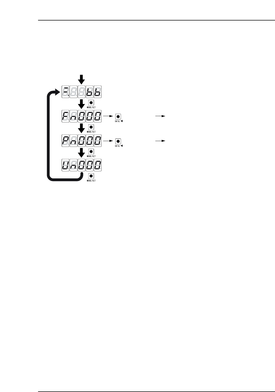
Basic mode selection and operation procedure
Alarm traceback display and Parameter check are two of the basic modes. Change the
basic mode at the panel operator to check operation status, parameters, or alarm
traceback display.
1. Push [MODE/SET] to select a basic mode in the following order.
2. Push [DATA/SHIFT] and [UP] or [DOWN] to select the desired parameter
number. In this status, push and hold [DATA/SHIFT] for more than 1 second to
display the contents of the selected parameter number in the selected mode.
XP1MA028E
Power ON
Push the MODE/SET key.
The basic mode is selected in the following order.
Status display mode
Push for more
than 1 sec.
Fn000
: Alarm traceback data
display mode
Push
Push
Push
Push
Push for more
than 1 sec.
Pn000 : Parameter setting mode
(DATA/SHIFT)
(DATA/SHIFT)
Part 4 Chapter 1 Servo Amplifier Adjustments
Edition 3.0 4-1-9 XP-142E Mechanical Reference

Status display mode
XP1MA029E
1
1
2
2
3
3
4
4
5
5
6
6
7
7
Bit data
Bit data
No.
Bit dataDisplay
In Speed/Torque Control Mode In Position Control Mode
Lit when SERVOPACK control
power is ON.
Display
Lit for base block. Not lit when
servo is ON.
Lit when the difference between
the servo motor speed and
reference speed is below the
value set in Pn503.
Always ON in torque control mode.
Lit if motor speed exceeds preset
value.
Not lit if motor speed is below
the setting. (Std. value: Pn502)
Lit if input speed reference exceeds
preset value.
Not lit if input speed reference is
below preset value.
Preset value: Set in Pn502.
Lit if input torque reference exceeds
preset value. Not lit if input torque
reference is below preset value.
Preset value: 10% rated torque.
Lit when main power supply circuit
is normal. Not lit when power is OFF.
Control Power
ON
Baseblock
Speed
Coincidence
(/V-CMP)
Detected
Rotation
(/TGON)
Speed
Reference
Input
Torque
Reference
Input
Power
Ready
Control
Power ON
Baseblock
Positioning
Completion
(/COIN)
Rotation
Detection
(/TGON)
Reference
Pulse Input
Error Counter
Clear Signal
Input
Power
Ready
Code
(Factory setting is 10min. )
-1
(Factory setting is 20min )
-1
(Factory setting is 20min )
-1
Lit when SERVOPACK control
power is ON.
Lit for base block. Not lit when
servo is ON.
Lit if error between position refer-
ence and actual motor position is
below preset value.
Not lit if error between position ref-
erence and actual motor position
exceeds preset value.
Preset value: Set in Pn522
(Factory setting is 7 pulses).
Lit if motor speed exceeds preset
value. Not lit if motor speed is below
preset value.
Preset value: Set in Pn502.
Lit if referece pulse is input.
Not lit if no reference pulse is input.
Lit when error counter clear signal
is input.
Not lit when error counter clear
signal is not input.
Lit when main power supply circuit
is normal. Not lit when power is OFF
(Standard setting: 20min )
-1
Part 4 Chapter 1 Servo Amplifier Adjustments
Edition 3.0 4-1-10 XP-142E Mechanical Reference