LmrXP142机械手册.pdf - 第123页
Part 5 Chapter 1 Servo System Troubleshooting Edition 3.0 5-1-24 XP-142E Mechanical Reference AC Servopack Check List for Troubleshooting Alarm Alarm Name Status Cause Remedy A.C91 Encoder Communications Position Data Er…
Part 5 Chapter 1 Servo System Troubleshooting
Edition 3.0 5-1-23 XP-142E Mechanical Reference
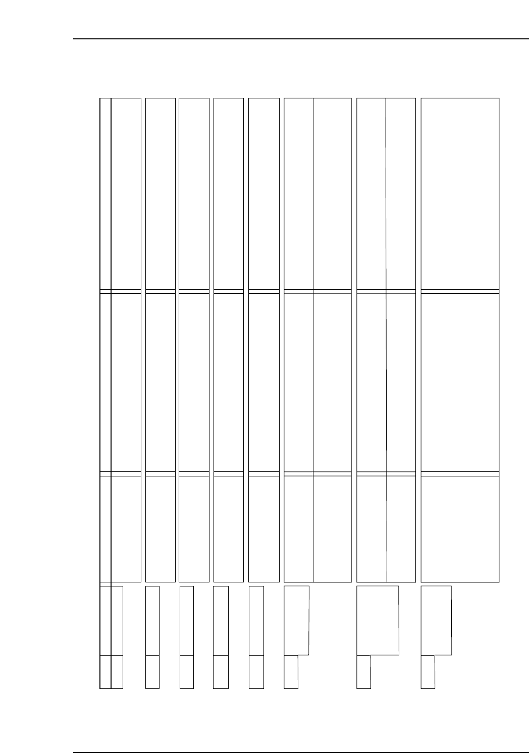
AC Servopack Check List for Troubleshooting
Alarm Alarm Name Status Cause Remedy
A.bF0 System Alarm 0 • Occurred when the control
power supply was turned
ON.
• A SERVOPACK board fault occurred. • Replace the SERVOPACK.
A.bF1 System Alarm 1 • Occurred when the control
power supply was turned
ON.
• A SERVOPACK board fault occurred. • Replace the SERVOPACK.
A.bF2 System Alarm 2 • Occurred when the control
power supply was turned
ON.
• A SERVOPACK board fault occurred. • Replace the SERVOPACK.
A.bF3 System Alarm 3 • Occurred when the control
power supply was turned
ON.
• A SERVOPACK board fault occurred. • Replace the SERVOPACK.
A.bF4 System Alarm 4 • Occurred when the control
power supply was turned
ON.
• A SERVOPACK board fault occurred. • Replace the SERVOPACK.
NP1MT020E
22
A.C10 Servo Overrun
Detected
• Occurred when the control
power supply was turned
ON.
• Occurred when the servo
was ON or a reference
was input.
• A SERVOPACK board fault occurred.
• The order of phase-U, -V, and -W in the
servomotor wiring is incorrect.
• An encoder fault occurred.
• A SERVOPACK fault occurred.
• Replace the SERVOPACK.
• Correct the servomotor wiring.
• Replace the servomotor.
• Replace the SERVOPACK
A.C80
Absolute Encoder
Clear Error and
Multi-turn Limit
Setting Error
• Occurred when the control
power supply was turned
ON.
• Occurred when an
encoder alarm was
cleared and reset.
• An encoder fault occurred.
• A SERVOPACK board fault occurred.
• An encoder fault occurred.
• A SERVOPACK board fault occurred.
• Replace the servomotor.
• Replace the SERVOPACK.
• Replace the servomotor.
• Replace the SERVOPACK.
A.C90 Encoder
Communications
Error
• Occurred when the control
power supply was turned
ON or during operation.
• The encoder wiring and the contact are
incorrect.
• Noise interference occurred due to incorrect
encoder cable specification.
• Noise interference occurred because the
wiring distance for the encoder cable is too
long.
• Correct the encoder wiring.
• Use tinned annealed copper twisted-pair or
twisted-pair shielded wire with a core of at least
0.12 mm (0.0002 in ).
• The wiring distance must be 20 m (65.6 ft) max.
Part 5 Chapter 1 Servo System Troubleshooting
Edition 3.0 5-1-24 XP-142E Mechanical Reference
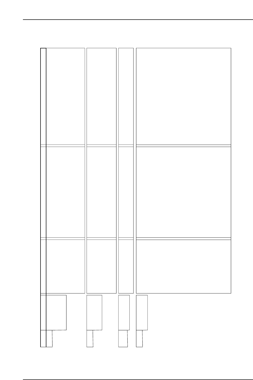
AC Servopack Check List for Troubleshooting
Alarm Alarm Name Status Cause Remedy
A.C91 Encoder
Communications
Position Data
Error
• Occurred when the control
power supply was turned
ON or during operation.
• The noise interference occurred on the signal
line because the encoder cable is bent and
the sheath is damaged.
• The encoder cable is bundled with a
high-current line or near a high-current line.
• The FG varies because of the influence from
machines on the servomotor side, such as
welder.
• Correct the encoder cable layout.
• Correct the encoder cable layout so that no surge
is applied.
• Make the grounding for the machine separately
from PG side FG.
A.C92 Encoder
Communications
Timer Error
• Occurred when the control
power supply was turned
ON or during operation.
• Noise interference occurred on the signal line
from the encoder.
• Excessive vibration and shocks were applied
to the encoder.
• An encoder fault occurred.
• A SERVOPACK board fault occurred.
• Take a measure against noise for the encoder
wiring.
• Reduce the machine vibration or mount the
servomotor securely.
• Replace the servomotor.
• Replace the SERVOPACK.
A.CA0 Encoder
Parameter Error
• Occurred when the control
power supply was turned
ON.
• An encoder fault occurred.
• A SERVOPACK board fault occurred.
• Replace the servomotor.
• Replace the SERVOPACK.
A.Cb0 Encoder
Echoback Error
• Occurred when the control
power supply was turned
ON or during operation.
• The encoder wiring and contact are incorrect.
• Noise interference occurred due to incorrect
encoder cable specifications.
• Noise interference occurred because the
wiring distance for the encoder cable is too
Iong.
• Noise interference occurred on the signal line,
because the encoder cable is bent and the
sheath is damaged.
• The encoder cable is bundled with a
high-current line or near a high-current line.
• The FG varies because of the influence from
the servomotor side machines, such as welder.
• Noise interference occurred on the signal line
from the encoder.
• Excessive vibration and shocks to the
encoder was applied.
• An encoder fault occurred.
• A SERVOPACK board fault occurred.
• Correct the encoder wiring.
• Use tinned annealed copper twisted-pair or
twisted-pair shielded wire with a core of at least
0.12 mm (0.002 in ).
• The wiring distance must be 20m (65.6 ft) max.
• Correct the encoder cable layout.
• Correct the encoder cable layout so that no surge
is applied.
• Ground the machine separately from PG side FG.
• Take measures against noise for the encoder
wiring.
• Reduce the machine vibration or mount the
servomotor securely.
• Replace the servomotor.
• Replace the SERVOPACK.
NP1MT021E
22
Part 5 Chapter 1 Servo System Troubleshooting
Edition 3.0 5-1-25 XP-142E Mechanical Reference
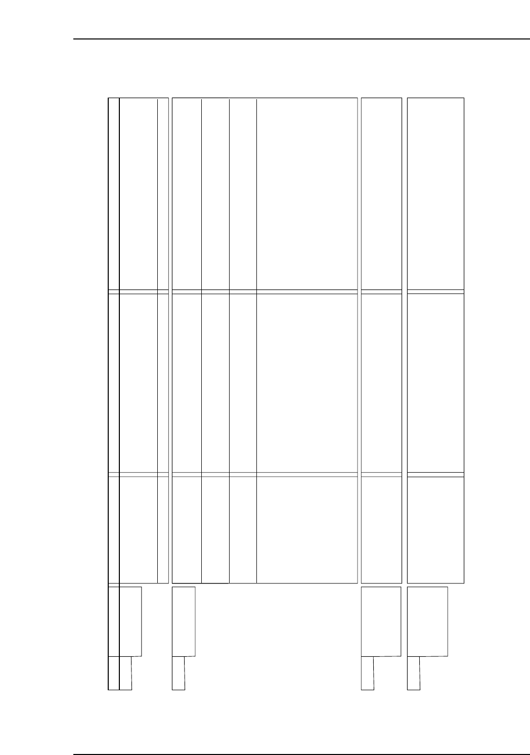
AC Servopack Check List for Troubleshooting
Alarm Alarm Name Status Cause Remedy
A.CC0 Multi-turn Limit
Disagreement
• Occurred when the control
power supply was turned
ON.
• Occurred during operation.
• The parameter settings for the SERVOPACK
are incorrect.
• The multiturn limit value for the encoder is not
set or was changed.
• A SERVOPACK board fault occurred.
• Correct the setting of Pn205 (0 to 65535).
• Execute Fn013 at the occurrence of alarm.
• Replace the SERVOPACK.
A.d00 Position Error
Pulse Overflow
• Occurred when the control
power supply was turned
ON.
• Occurred at the
servomotor high-speed
operation.
• The servomotor did not
run with position reference
input.
• Normal movement, but
occurred with a long
distance reference input.
• A SERVOPACK board fault occurred.
• The contact in the servomotor U, V, and W
wirings is faulty.
• A SERVOPACK board fault occurred.
• Wirings of the servomotor U. V. and W are
incorrect.
• A SERVOPACK board fault occurred.
• The SERVOPACK gain adjustment is
improper.
• The position reference pulse frequency is too
high.
• Setting of the parameter Pn520 (Position
Error Pulse Overflow Alarm Level) is incorrect.
• The servomotor specifications do not meet
the load conditions such as torque and
moment of inertia.
• Replace the SERVOPACK.
• Correct the servomotor wiring.
• Correct the encoder wiring.
• Replace the SERVOPACK.
• Correct the servomotor wiring.
• Replace the SERVOPACK.
• Increase the speed loop gain (Pn100) and
position loop gain (Pn102).
• Adjust slowly the position reference pulse
frequency.
• Apply the smoothing function.
• Correct the electronic gear ratio.
• Set the parameter Pn520 to proper value.
• Reconsider and correct the load and servomotor
capacity.
A.d01 Position Error
Pulse Overflow
Alarm at Servo
ON
• Occurred when the control
power supply was turned
ON.
• Excessive position errors accumulated while
the servo is OFF
• With the setting not to clear the errors while
the servo is OFF, the servomotor was running.
• Do not run the servomotor in servo OFF status.
• Make the setting so that the errors are cleared
while the servo is OFF.
• Adjust the detection level.
A.d02 Position Error
Pulse Overflow
Alarm by Speed
Limit at Servo ON
• Occurred when the
servomotor was running.
• The servo turned ON with accumulated errors,
and reference pulse was input during
operation at the speed limit, therefore, the
errors exceeded the Position Error Pulse
Overflow Alarm Level (Pn520).
• Do not run the servomotor in servo OFF status.
• Make the setting so that the errors are cleared
while the servo is OFF.
• Correct the detection level.
• Adjust the speed limit level (Pn529) when servo
turns ON.
NP1MT022E