CP43维护手册.pdf.pdf - 第103页
10 – 3 V ersion 7.0 Chapter 10 Cam Box 10.2.2 The Index Cam The index cam rotates the 12 placing heads. The index cam rotation moves the 12 cam followers attached to the upper part of the rotary head, causing the placing…
Chapter 10 Cam Box
10.2The Workings of the Cam
The cam box consists of nine cams, one index cam and one cylinder cam.
The purpose of these items are explained here.
10.2.1The Nine Cams
The nine cams are used in the operation of the feeders and placing
heads.
Five cams operate at station 1 controlling the following areas of
operation:
• Feeder tape advance/retract
• Feeder tape advance
• Feeder parts push-up
• End tape cut
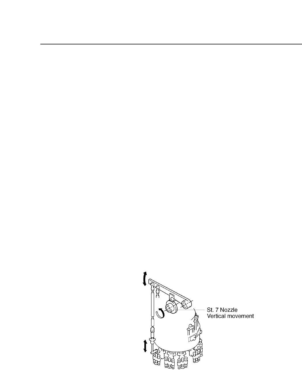
• Vertical movement of the nozzle
The remaining four each operate one of these functions:
• Pre-theta (vertical movement) at station 3
• Fine-theta (vertical movement) at station 6
• Nozzle (vertical movement) at station 7
• Nozzle changeover (vertical movement) at station 11
Fig. 10-2 The Operation of the 9 Cams
The cam lever is connected to the rod. The rod is connected to the
feeder or the placing head.
10 – 2
Version 7.0
CP IV-3 Maintenance
10 – 3
Version 7.0
Chapter 10 Cam Box
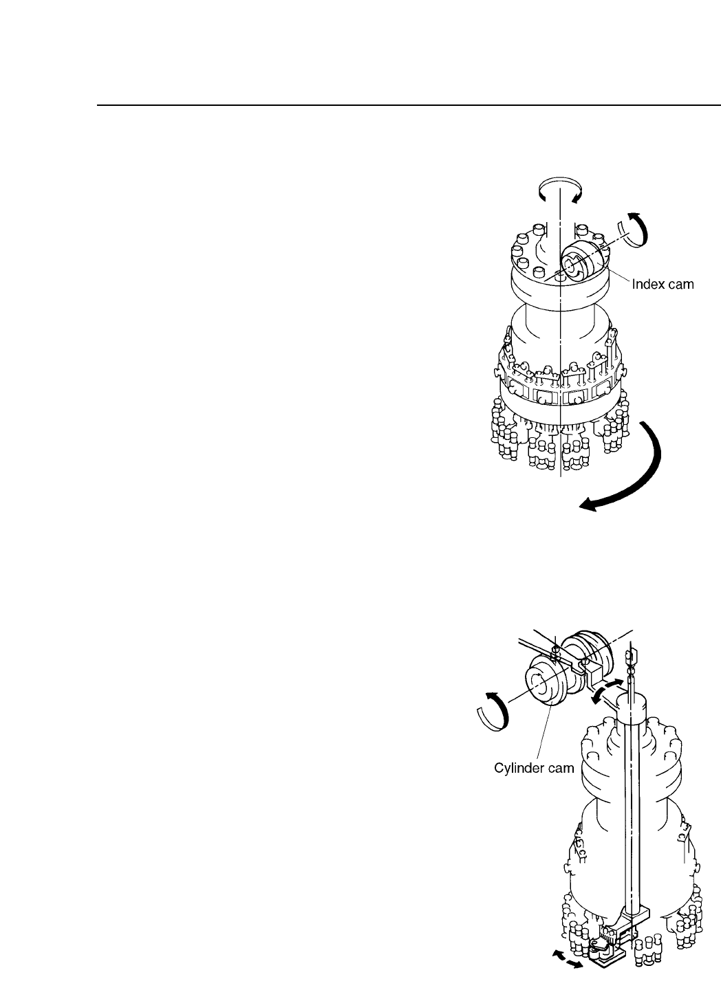
10.2.2The Index Cam
The index cam rotates the
12 placing heads. The
index cam rotation moves
the 12 cam followers
attached to the upper part
of the rotary head,
causing the placing heads
to move in increments of
360°/12 = 30°.
Fig. 10-3 Index Cam Operation
10.2.3The Cylinder Cam
The cylinder cam is used for
selecting the L,M,or S nozzle
that used in the nozzle change
operation at station 11. The
curvature of the cylinder cam
drives the cylinder which in
turn drives the shaft and the
connected lever. This lever
carries out the nozzle change
operation.
The cylinder cam is also used
for selecting the direction of
rotation for the PQ operation at
station 3. The curvature of the
cylinder cam drives a lever
which is connected to a shaft
which in turn drives the gear
used for carrying out PQ
rotation at station 3.
Fig. 10-4 Cylinder Cam Operation
CP IV-3 Maintenance
Chapter 10 Cam Box
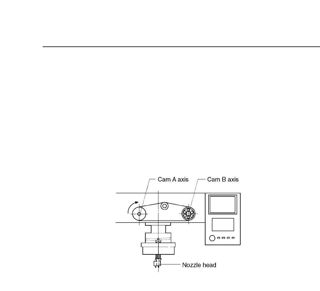
10.3Synchronizing the Cam Axes
In the cam box, the cams are attached to two cam shafts. If there is a
phase shift between these two cams, parts may not be placed. The
following procedures explain how to synchronize the cam axes.
(1) When making these adjustments, make sure that the power is turned
OFF.
(2) Check that the tension of the timing belt between cam axes A and B is
set to the correct value. Please refer to section 10.4 for more
information.
Fig. 10-5 Schematic of Cam Axes A and B
10 – 4
Version 7.0
CP IV-3 Maintenance