CP43维护手册.pdf.pdf - 第108页
Chapter 10 Cam Box (9) Place a hex wrench on the bolt in the center of cam axis B, and while watching the dial gauge, turn the handle until station 7's cam nozzle vertical cam lever stops. While doing this, make sur…
10 – 7
Version 7.0
Chapter 10 Cam Box
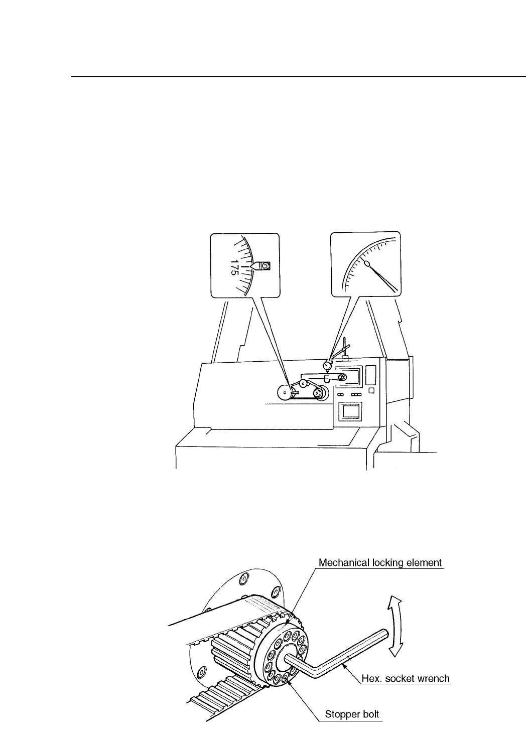
(7) While looking at the dial gauge, turn the handle to the left until there
is no change in the dial gauge indicator, when the dial gauge reading
is 0. This point is a point before placement. At this point, cam axes A
and B are synchronized. This also holds true for cam axis B, for
station 7's nozzle vertical cam lever. When the dial gauge indicator is
0, the axes are synchronized. If the axes are synchronized at this
point, the procedure is finished. If they are not continue with
procedures 8 thru 11. See figure 10-9 for more details.
Fig. 10-9 When Cam Axis A and B are Synchronized
(8) Manually turn the cam handle so that the angle is 175°. Loosen the
span ring bolts on the front head of cam axis B. See figure 10-10 for
more details.
Fig. 10-10 Rotation of Cam B
CP IV-3 Maintenance

Chapter 10 Cam Box
(9) Place a hex wrench on the bolt in the center of cam axis B, and while
watching the dial gauge, turn the handle until station 7's cam nozzle
vertical cam lever stops. While doing this, make sure that cam axis A
does not turn. See figure 10-10 for more details.
(10)Retighten the six span ring bolts. Tighten them in the correct
direction. When retightening the bolts, make sure that there is any
shift in cam axis A or B.
(11)Manually turn the cam axis, when the dial gauge indicator on cam
axis B stops moving, check that the cam angle is 175°. If the cam angle
is not 175° then repeat steps 8 thru 11.
Note: Cam axis A and B should be synchronized to within 2 to 3°.
10 – 8
Version 7.0
CP IV-3 Maintenance
10 – 9
Version 7.0
Chapter 10 Cam Box
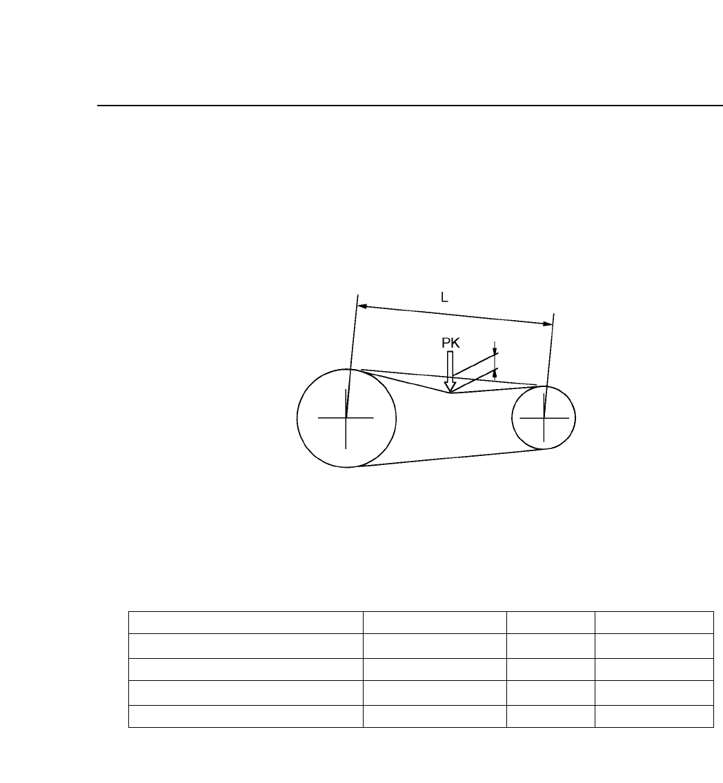
10.4Adjusting the Tension on the Timing Belt
The following tensions are measured by placing a push-pull gauge in the
center of the belt, as shown in table 10-1 and figure 10-11.
Alternately, use a tension meter to adjust the tension to a suitable
frequency .
Fig. 10-11 Timing Belt Tension Adjustment
Table 10-1 Timing Belt Displacements
Note: Since two belts are used for Central axis and cam axis A and Cam axis A
and cam axis B, take the average of the two values.
Cam motor axis and central axis
Central axis and cam axis switch
Central axis and cam axis A
Cam axis A and cam axis B
Between Axis
Displacement (mm)
Frequency (Hz)
2.2
1.5
3.9
4.0
2.7
0.3
1.8
1.8
140 ± 5
235 ± 5
91 ± 5
89 ± 5
Force. (kgf)
CP IV-3 Maintenance