CP43维护手册.pdf.pdf - 第28页
Chapter 2 Setting Up the CP IV -3 2.6 MCS2/H Line Descriptor Registration For a detailed description of the line descriptor refer to the MCS2/H Operation Manual, Part 2, Chapter 1. From the UCI main menu, select the [Edi…
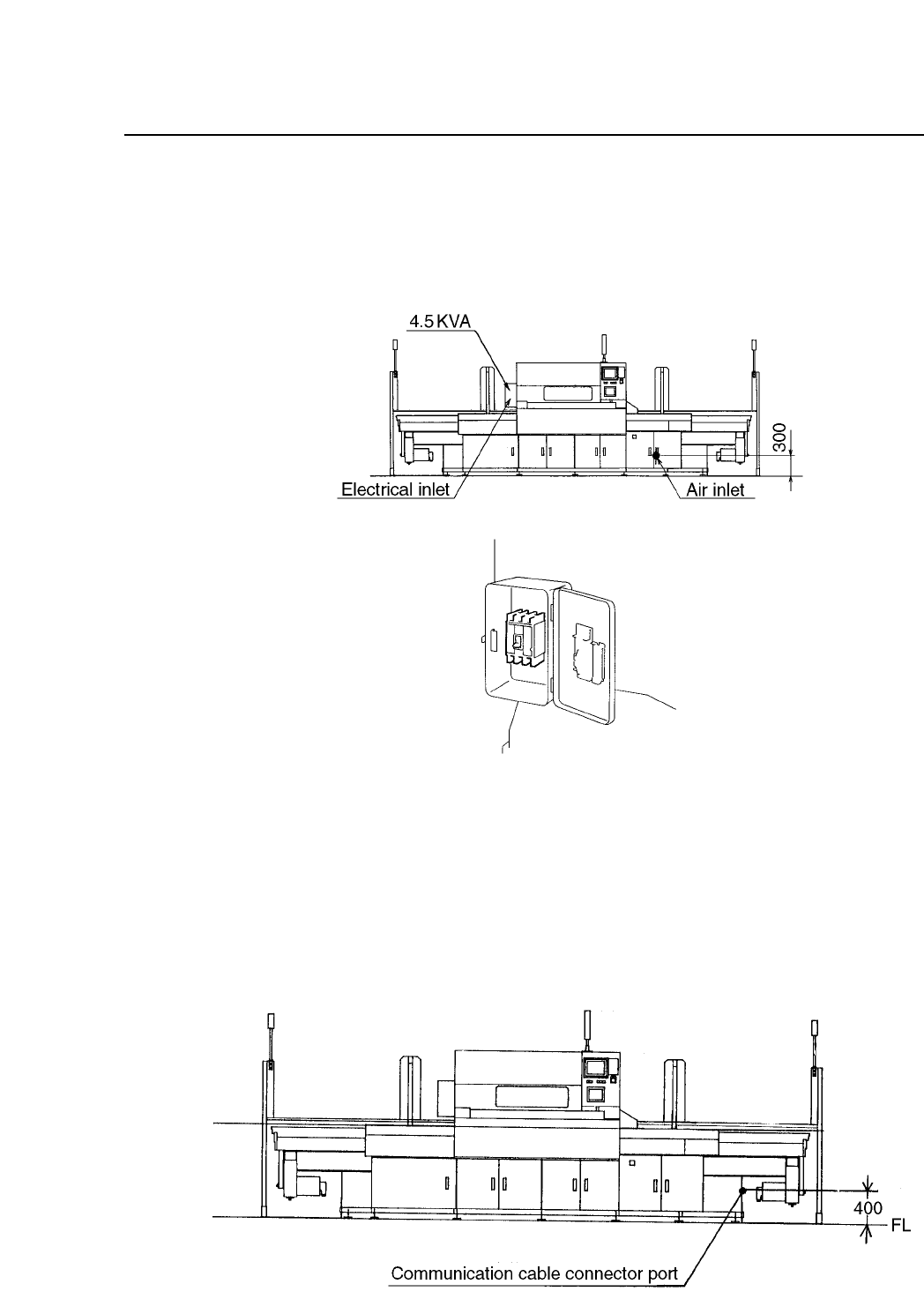
Chapter 2 Setting Up the CP IV-3
Run the power supply cable through the opening at the bottom of the
machine on the left-hand side (when viewing from the front) as shown in
figure 2-7. Connect the three phase cables and the earth cable to the
primary side of the main breaker.
Fig. 2-7 Entry Position of Three Phase and Earth Cables
2.5 Connecting the Communication Cable
Connect the CP IV-3 to the MCS 30 computer port specified in the line
descriptor, using the communication cable supplied with the CP IV-3. The
CP connector port is located on the right side of the machine, as shown
below.
Fig. 2-8 Connecting the Communication Cable
2 – 5
Version 8.0

Chapter 2 Setting Up the CP IV-3
2.6 MCS2/H Line Descriptor Registration
For a detailed description of the line descriptor refer to the MCS2/H
Operation Manual, Part 2, Chapter 1.
From the UCI main menu, select the [Editor] and [Line Descriptor]
commands, in that order. Then select the appropriate data for each item
displayed on the monitor, as shown below.
Heading Setting Comments
M/C Free Enter any number between 1 and 255
port# Free Enter the RS232C port connector number
(1-16)
Mon_port 0 Unsupported
Active 1 To communicate with MCS30 computer
Line Free Enter a line number (1-16)
Line_name Free Enter six or fewer characters to serve as a line
nickname
Mc_name Free Enter six or fewer characters to serve as a
machine nickname
Mc_type 28 The machine number in MCS2/H is 28.
Protocol 0 No communication protocol is to be used
Baud Rate 0 Baud rate is set to 9,600 bits per second
Bit_char 0 Character data length is set to 8 bits
Parity 0 Parity function is disabled
Parity_check 0 Parity check function is disabled
After all entries have been completed, save the line descriptor.
Note: After the MCS2/H line descriptor has been modified, the computer must be
shut down once (following the normal shutdown procedure) and then
rebooted. The newly input data will not take effect until this is done.
2 – 6
Version 4.0

Chapter 2 Setting Up the CP IV-3
2.7 Checking the Three Phase Cable Wiring
By checking the direction of motor rotation, the wiring of the machine can
also be checked. If the motor direction is correct then the wiring is also
correct. This check can be performed without the 200V power supply.
(1) Engage the 100V power supply.
(2) Pull the station 8 spool out.
(3) Place one finger on the tip of the nozzle and check for air suction. If
air suction is detected, the wiring has been set up correctly, and the
motor is rotating in the correct direction. If air is expelled, change the
U and V phase of the three-phase cable wiring and repeat steps (1) to
(3) to check for air suction.
2 – 7
Version 4.0