CP43维护手册.pdf.pdf - 第106页
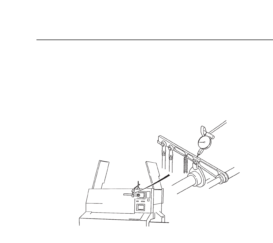
Chapter 10 Cam Box (5) Manually turn the cam handle until cam axis A's angle is 175°. (6) Set a dial gauge on station 7's nozzle vertical cam lever and align the dial gauge to 0. See figure 10-8 for mor e detai…
10 – 5
Version 7.0
Chapter 10 Cam Box
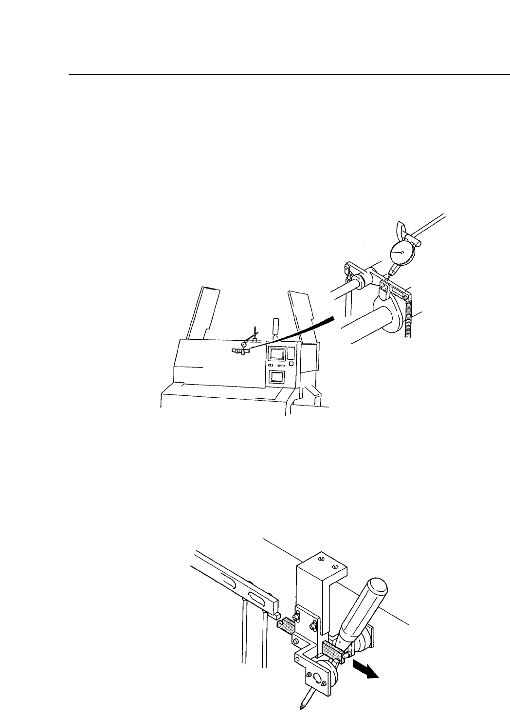
(3) Check the dial gauge on cam axis A. Manually turn the cam handle
until the cam angle is 245°, and set a dial gauge on Station 1's waste
tape cutter cam lever on cam axis A. Check that when the cam angle
is at 245°, the cam is at its maximum diameter (the cam lever is at its
highest point). If the position has shifted, set a dial gauge on the front
and rear of the machine, and make the necessary adjustments. See
figure 10-6 for more details.
Fig. 10-6 Dial Gauge on Waste Tape Cutter Cam Lever at Station 1
(4) With the cam angle at 0°, remove the stopper from station 7's nozzle
vertical cam lever, and insert a screw driver to substitute for the
absence of the stopper.
Fig. 10-7 Removing the Stopper from Station 7's Cam Lever
CP IV-3 Maintenance
Chapter 10 Cam Box
(5) Manually turn the cam handle until cam axis A's angle is 175°.
(6) Set a dial gauge on station 7's nozzle vertical cam lever and align the
dial gauge to 0. See figure 10-8 for more details.
Note: When the cam angle is 0°, and a dial gauge is set on station 7's nozzle
vertical cam lever, when the cam lever raises, be careful that the tip of the
dial gauge is not damaged. Be sure to set the cam angle to 175°.
Fig. 10-8 Dial Gauge Nozzle Vertical Cam Lever at Station 7
10 – 6
Version 7.0
CP IV-3 Maintenance
10 – 7
Version 7.0
Chapter 10 Cam Box
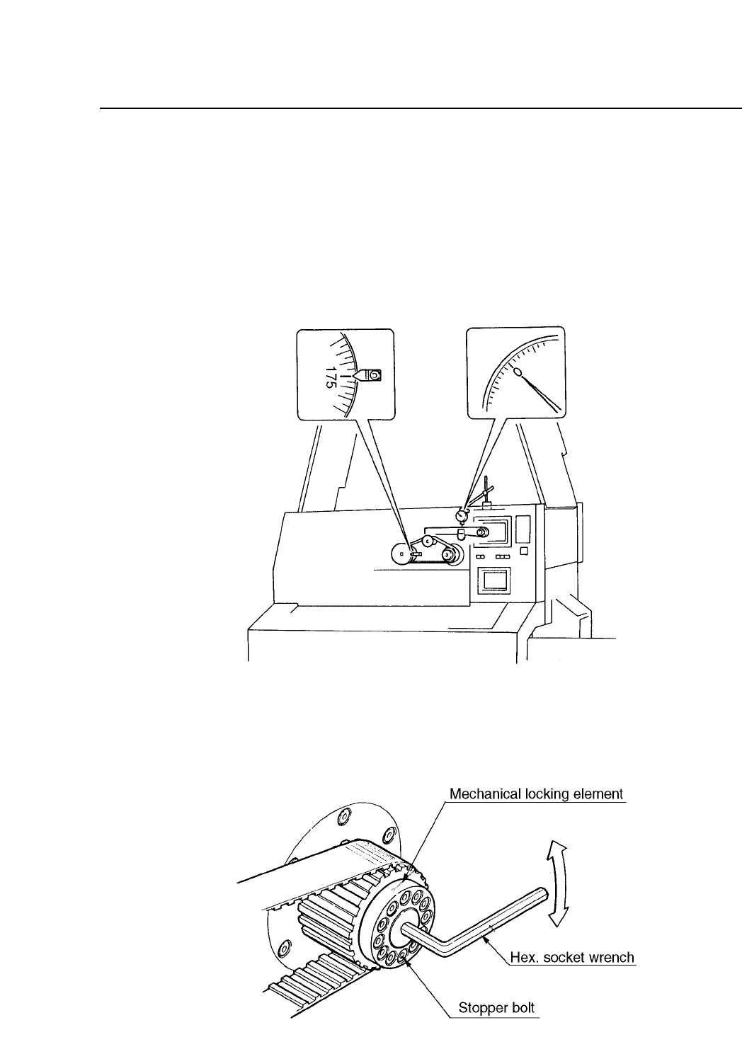
(7) While looking at the dial gauge, turn the handle to the left until there
is no change in the dial gauge indicator, when the dial gauge reading
is 0. This point is a point before placement. At this point, cam axes A
and B are synchronized. This also holds true for cam axis B, for
station 7's nozzle vertical cam lever. When the dial gauge indicator is
0, the axes are synchronized. If the axes are synchronized at this
point, the procedure is finished. If they are not continue with
procedures 8 thru 11. See figure 10-9 for more details.
Fig. 10-9 When Cam Axis A and B are Synchronized
(8) Manually turn the cam handle so that the angle is 175°. Loosen the
span ring bolts on the front head of cam axis B. See figure 10-10 for
more details.
Fig. 10-10 Rotation of Cam B
CP IV-3 Maintenance