CP43维护手册.pdf.pdf - 第20页
Chapter 1 Safety Guidelines 1.1.2 Checking the T ransformer Connections Remove the large attachment scr ews on the end cover on the left- hand side of the machine and take the cover off. Check that the main transformer i…
Chapter 1 Safety Guidelines
1. Safety Guidelines
Fuji made the safety of the operator one of the foremost priorities in the
designing of the FCP IV-3.
However, to ensure safety, the operator must follow the safety guidelines
described in this chapter.
1.1 Electrical Safety Guidelines
This section describes safety guidelines when working with the electric
power supply and transformers.
1.1.1 High Voltage Electricity Supply
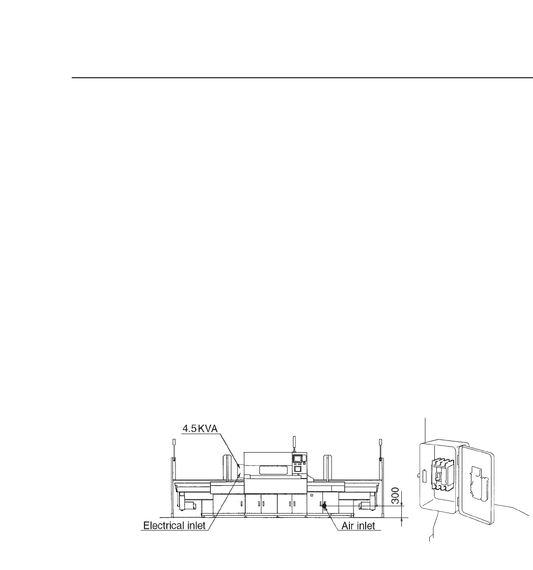
Run the power supply cable through the opening at the bottom of
the machine on the left-hand side (when viewing from the front) as
shown in figure 1-1. Connect the three phase cables and the earth
cable to the primary side of the main breaker.
Fig. 1-1 Position of the Three Phase and Earth Cables
Before performing machine inspection, always disengage the main
power source. Even if the main breaker is off, the primary voltage
is still active, so operators should be very careful.
Also, the machine should never be operated with the door open as
shown in figure 1-1.
1 – 1
Version 8.0
Chapter 1 Safety Guidelines
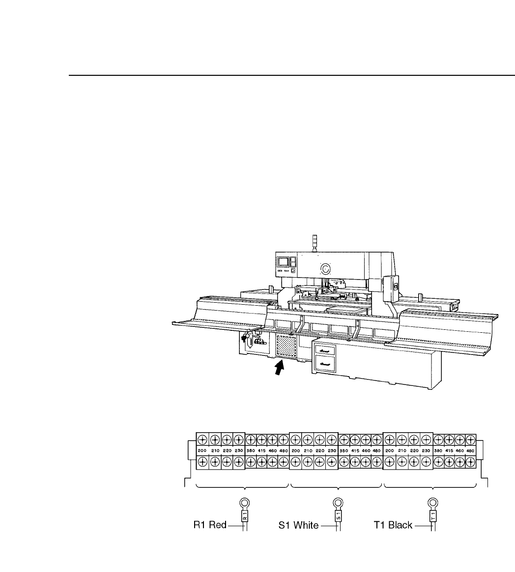
1.1.2 Checking the Transformer Connections
Remove the large attachment screws on the end cover on the left-
hand side of the machine and take the cover off. Check that the
main transformer is set to the specified input voltage. If the
transformer is set to an incorrect input value electrical parts may be
damaged. Figure 1-2 shows the positioning of the transformer taps.
Fig. 1-2 Position of the Transformer and Transformer Taps
1 – 2
Version 1.0
Chapter 1 Safety Guidelines
1.2 Emergency Stop Buttons
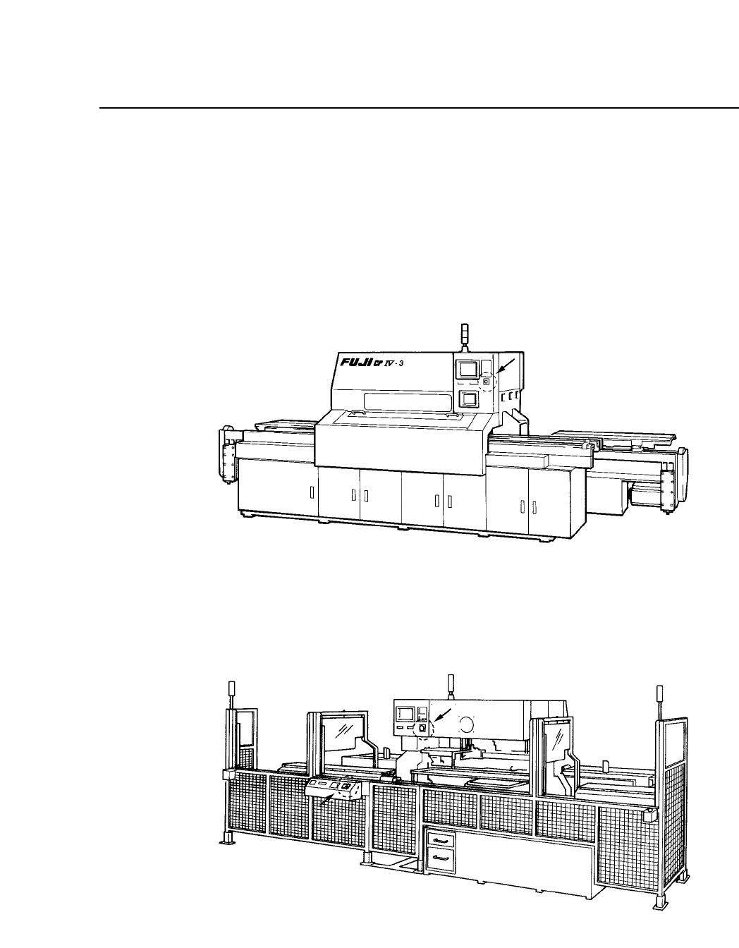
To stop machine operation immediately to counter an emergency
situation, press one of the three red round emergency stop buttons on the
machine. One of the emergency stop buttons is on the front of the
machine near the control panel (see figure 1-3) and the other two are on
the back of the machine (see figure 1-4).
Fig. 1-3 Emergency Stop Button on Front of Machine
Fig. 1-4 Emergency Stop Buttons on Back of Machine
1 – 3
Version 1.0