CP43维护手册.pdf.pdf - 第123页
13 – 1 V ersion 7.0 Chapter 13 Changeover 13. Changeover This chapter describes changeover procedur es for the CP IV -2. These include the following: • program changeover • XY table guide rail width changeover • in and o…
Chapter 12 VME Boards
12.1Control Box 2 Optional Boards
• Conveyor width control servo board VM1530 (Optional)
This is an additional board required when the HELPS manufacturing
support system is used. It controls conveyor width.
• 4 channel communication board VME070 (Optional)
This is an additional board required when the HELPS manufacturing
support system is used. It carries out the communication between
LMS and the bar code reader or pattern code reade and the Handy
Terminal.
12.2Other Controls for Control Box 2
• Loader programmable controller MX100
Programmable controller for the board transport loader system.
12.3Control Box 1
The direct I/O is located inside control box 1.
Fig. 12-3 Direct I/O Location
• Direct I/O board
The I/O board receives input from sensors and switches on the
machine and sends the signals on to the CPU. In addition, this board
receives the outputs from the CPU and uses them to control the
solenoids and relays. This direct I/O board is directly connected to
the VME Interface (MX100CP91) in the VME board in control box 2.
12 – 4
Version 7.0
CP IV-3 Maintenance

13 – 1
Version 7.0
Chapter 13 Changeover
13.Changeover
This chapter describes changeover procedures for the CP IV-2. These include
the following:
• program changeover
• XY table guide rail width changeover
• in and out conveyor width changeover
• tape feeder changeover
• back-up pin position changeover
• board pin pitch changeover
• pin changeover (when changing pin diameter)
13.1Program Changeover
When the next production program already exists in the machine, press
[PROGRAM], [CHANGE], [# of the program] and [CR]. This will move
the program from the background to the foreground.
When the next program does not exist in the machine, transmit it from
MCS to the background of the machine. Once it is in the machine's
background, press [PROGRAM], [CHANGE], [# of the program], and
[CR] to move it from the background to the foreground.
13.2Conveyor Width Changeover
Width changeover for the XY table guide rail, in conveyor and out
conveyor is performed in one operation. This operation is performed
according to the following procedure:
(1) Press [LOADER], [LOADING PSTN] and [START].
The XY table will line up with the in and out conveyors.
(2) Press [LIFTER ▲]. The XY table is raised to the same height as the
OUT conveyor.
(3) Turn the conveyor width changeover handle on the out conveyor to
align the conveyor width to that of the board. Leave 0.5 ~ 1.0 mm so
that the board is not squeezed in too tightly.
CP IV-3 Maintenance
Chapter 13 Changeover
(4) Press [LIFTER ▼]. The XY table is lowered to the height for placing.
Note: Be sure to check the position of the back-up pins after a width change.
The back rails may collide with the pins resulting in damage when the
lifter table is lowered.
13.3Tape Feeder Changeover
Place the tape feeders on the device table as indicated by the program.
13.4Back-up Pin Position Changeover
(1) Press [LOADER], [LOADING PSTN] and [START].
The Y table will line up with the in and out conveyors..
(2) Press [LIFTER ▲]. The XY table is raised to the same height as the
OUT conveyor.
(3) Change the position of the back-up pins.
(4) Confirm that the the back-up pins will not collide with the guide rail
when the XY table is lowered. If collision is possible, move the back-
up pins.
(5) Press [LIFTER ▼]. The XY table is lowered to the height for placing.
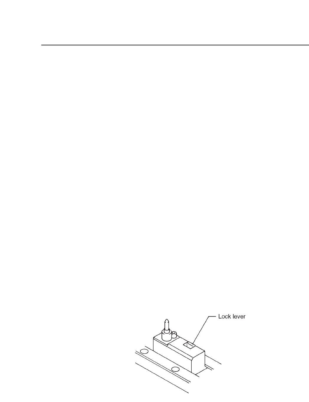
13.5Board Pin Pitch Changeover
Push back the lock lever and adjust the position of the pin pitch holder to
the pin pitch of the board.
Fig. 13-1 XY Table
13 – 2
Version 7.0
CP IV-3 Maintenance