CP43维护手册.pdf.pdf - 第63页
5 – 21 V ersion 6.0 Chapter 5 The T welve Stations 5.2 Station 2 At Station 2, sensors check for the presence of lar ge parts. Misalignment of the tape with the pickup point is one cause of pickup errors when working wit…
Chapter 5 The Twelve Stations
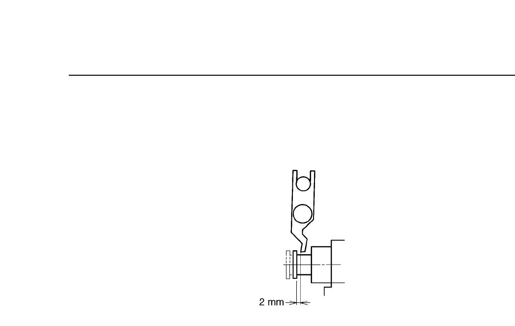
(5) Return the cam angle to 0°. With the spool flange returned to
its original position, confirm that the gap between the spool
flange and the valve ON/OFF lever is 2 mm.
Fig. 5-21 Spool Flange and Valve ON/OFF Lever Gap
(Cam Angle 0°)
5 – 20
Version 6.0
CP IV-3 Maintenance
5 – 21
Version 6.0
Chapter 5 The Twelve Stations
5.2 Station 2
At Station 2, sensors check for the presence of large parts.
Misalignment of the tape with the pickup point is one cause of pickup
errors when working with large parts. If a sensor determines a part to be
missing, it may in fact be misaligned with the pickup point and thus
vulnerable to being hit by the waste tape cutter. Therefore, if a part is
judged to be missing, the machine stops to prevent the loss that might be
incurred by having a large, expensive part damaged by the waste tape
cutter.
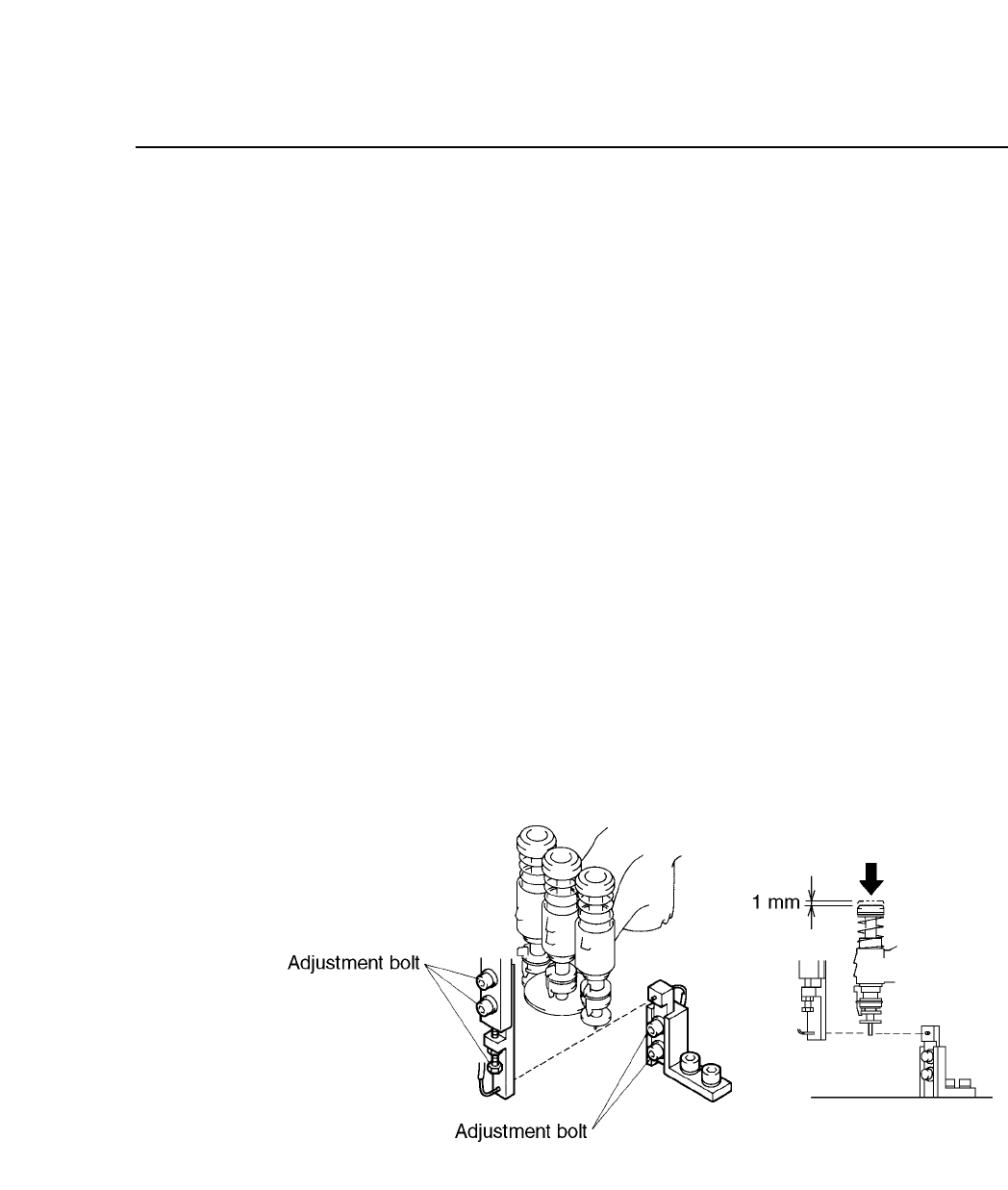
Follow the procedure below to adjust the station 2 sensors.
(1) Engage only the 100V power supply.
(2) Attach the cam handle on the handle shaft. Turn the handle until the
cam angle indicator reads 230°.
(3) With the cam angle at 230°, lower the L nozzle 1 mm (measure with a
ruler as shown in the illustration below). Adjust so that the tip of the
L nozzle will trigger the sensor.
Fig. 5-22 Large Parts Presence Check Sensor
CP IV-3 Maintenance
Chapter 5 The Twelve Stations
5.3 Station 3
At station 3, the part is rotated to the initial theta axis position. This
function is termed “pre-rotation” and abbreviated to Pθ. The pre-rotation
function rotates the part picked up at station 1 to approximately the angle
specified in the program. Pre-rotation reduces the cycle time by reducing
the time spent to perform fine rotational adjustment (Fθ) at station 6 after
vision processing has been performed at station 4.
However, pre-rotation can only be carried out in units of 90°; parts are
rotated +90°, 0°, or –90°. If a program calls for a part to be rotated 180°,
the part is first rotated either +90° or –90° at station 3. Then at station 6,
the part is rotated the remaining 90° plus the number of degrees necessary
for fine rotational adjustment. Thus parts that require 180° rotation
slightly lengthen cycle time.
Pre-rotation involves vertical movement as well as rotation in the θ
direction.
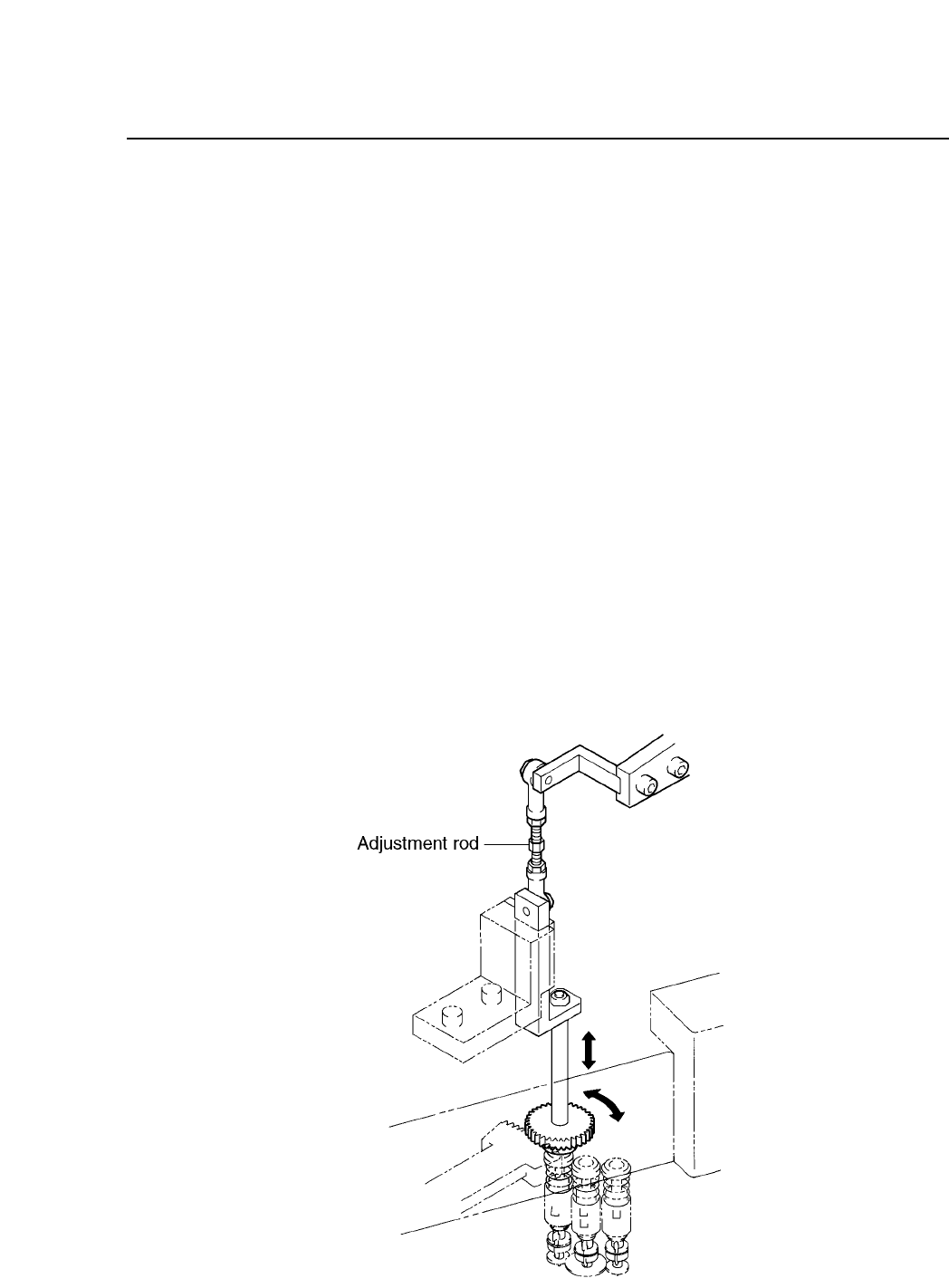
Pre-rotation is driven by cam and cylinder mechanisms. The cam drives a
lever, which drives a rod, which drives a lever, which drives the clutch,
which rotates the cylinder +90° or –90°.
Fig. 5-23 Pre-rotation (P
θ
) Mechanism at Station 3
5 – 22
Version 6.0
CP IV-3 Maintenance