CP43维护手册.pdf.pdf - 第62页
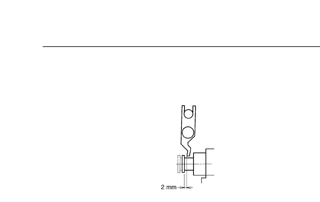
Chapter 5 The T welve Stations (5) Return the cam angle to 0°. W ith the spool flange returned to its original position, confirm that the gap between the spool flange and the valve ON/OFF lever is 2 mm. Fig. 5-21 Spool F…
5 – 19
Version 6.0
Chapter 5 The Twelve Stations
Follow the procedure below to adjust the ON/OFF operation of the
nozzle valve.
(1) Press [SET], [MANUAL], [I/O] and [EMERGENCY STOP] to
cut the 200V but still leaving the 100V power supply on.
(2) Enter the I/O map and press [OUT], [+Page]; then use the ▼ or
▲ key to move the cursor to the item titled “Y020 PICKUP SOL
ON”. Using the [ON/OFF] button, change the displayed “X”
to “O”. This operation turns off station 1’s solenoid stopper. If
the solenoid is not turned off, adjustment is impossible.
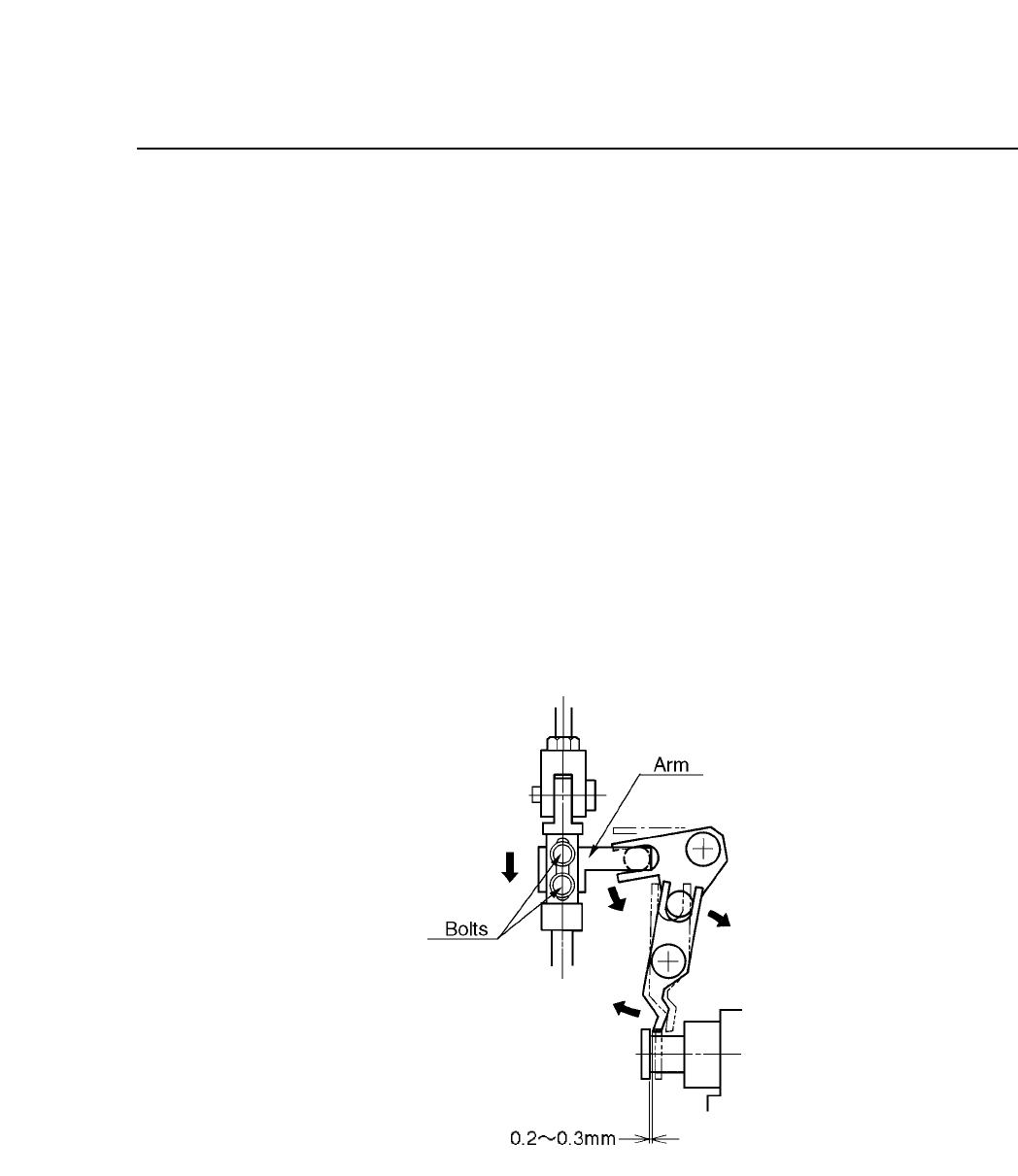
(3) Attach the cam handle to the cam shaft. Turn the handle until
the cam angle indicator reads 230°.
(4) With the cam angle at 230° and the spool pulled all the way
out, loosen the two bolts and adjust the vertical position of the
arm so that there is 0.2~0.3 mm between the spool flange and
the valve ON/OFF lever.
Fig. 5-20 Spool Flange and Valve ON/OFF Lever Gap
(Cam Angle 230°)
CP IV-3 Maintenance
Chapter 5 The Twelve Stations
(5) Return the cam angle to 0°. With the spool flange returned to
its original position, confirm that the gap between the spool
flange and the valve ON/OFF lever is 2 mm.
Fig. 5-21 Spool Flange and Valve ON/OFF Lever Gap
(Cam Angle 0°)
5 – 20
Version 6.0
CP IV-3 Maintenance
5 – 21
Version 6.0
Chapter 5 The Twelve Stations
5.2 Station 2
At Station 2, sensors check for the presence of large parts.
Misalignment of the tape with the pickup point is one cause of pickup
errors when working with large parts. If a sensor determines a part to be
missing, it may in fact be misaligned with the pickup point and thus
vulnerable to being hit by the waste tape cutter. Therefore, if a part is
judged to be missing, the machine stops to prevent the loss that might be
incurred by having a large, expensive part damaged by the waste tape
cutter.
Follow the procedure below to adjust the station 2 sensors.
(1) Engage only the 100V power supply.
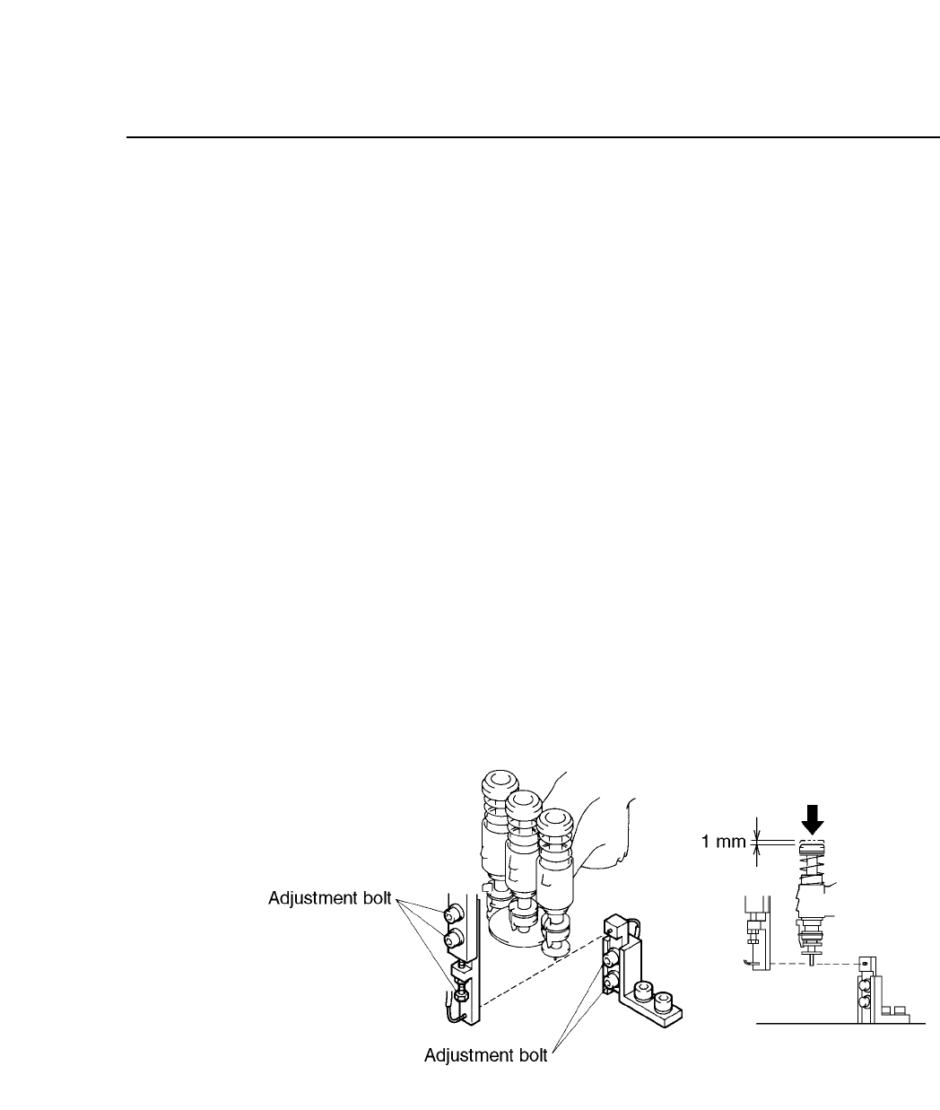
(2) Attach the cam handle on the handle shaft. Turn the handle until the
cam angle indicator reads 230°.
(3) With the cam angle at 230°, lower the L nozzle 1 mm (measure with a
ruler as shown in the illustration below). Adjust so that the tip of the
L nozzle will trigger the sensor.
Fig. 5-22 Large Parts Presence Check Sensor
CP IV-3 Maintenance