CP43维护手册.pdf.pdf - 第161页
20 – 1 V ersion 7.0 Chapter 20 Memory Board Installation 20. Memory Board Installation The user must initialize memory board RAM when a new boar d is installed. Initialize new boards only . Do not initialize a memory boa…

Chapter 19 Video Signal Gain and Offset
19.3Setting Gain and Offset
(1) Press [SET], [MANUAL] and [VISION]. An ID code must be entered
to access vision commands.
(2) Press [BRIGHT].
(3) Press [MARK CAMERA] to set gain and offset for the mark camera.
Press [NARROW VIEW] to set gain and offset for the narrow view
parts camera.
Press [WIDE VIEW] to set gain and offset for the wide view parts
camera.
When any of the above function keys is pressed, the monitor displays
a realtime image from the selected camera. The image changes
dynamically as gain and offset are adjusted.
(4) Press [SELECT] to choose between gain and offset adjustment.
Note: Refer to Part 3 of the CP IV-3 Operation Manual for details of the gain
and offset setting commands.
19 – 2
Version 7.0
CP IV-3 Maintenance
20 – 1
Version 7.0
Chapter 20 Memory Board Installation
20.Memory Board Installation
The user must initialize memory board RAM when a new board is
installed. Initialize new boards only. Do not initialize a memory board
that contains data.
20.1Initializing Memory Board RAM
Follow the steps below to initialize memory board RAM.
(1) Turn on the power and boot up the machine. Delete all production
programs from machine memory using the MCS “Delete M/C
program” command in the Transmission menu.
Note: Refer to the MCS/2 System Instruction Manual, Part 3, for a
detailed explanation of the “Delete M/C program” command.
(2) Turn the machine power off. Open the control box and put on the
anti-static wristband.
(3) Make sure that the SCSI ID switch settings on the board are correct
and that the jumpers on the VME rack are shorted. Mount the
memory board in the VME rack in the designated position.
Note: See section 4.5 for an explanation of SCSI ID switch settings and
VME rack jumpers.
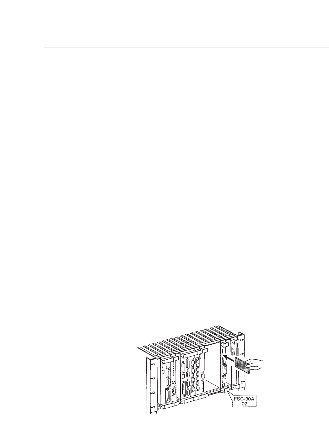
(4) Insert the vision software ROM memory card in the memory card slot
until the eject button sticks out. Attach the SCSI cable to the connector
on the board, as shown below.
Fig. 20-1 Attaching the SCSI Cable to the Board
CP IV-3 Maintenance

Chapter 20 Memory Board Installation
(5) Turn on the power and boot up the machine.
(6) Press [SET], [MANUAL] and [VISION]. An ID code must be entered
to access vision commands.
(7) Press [INSTALL].
(8) Press [INITIALIZE].
(9) Press [START] to initialize memory board RAM.
(10)After RAM is initialized, measure camera Proper data or load it from
a backup SRAM memory card.
Note: Refer to section 2.2 for instructions on loading camera Proper data
from SRAM memory card. Be especially careful to carry out the
procedures to confirm that data has loaded successfully. Be sure to
remove the SRAM memory card from the memory board and insert
the original ROM memory card before rebooting the machine.
(11)Turn off the power, then turn it back on and boot up the machine.
(12)Transmit a program from MCS to the machine and measure nozzle
centers.
20 – 2
Version 7.0
CP IV-3 Maintenance