CP43维护手册.pdf.pdf - 第88页
Chapter 5 The T welve Stations 5 – 46 V ersion 6.0 CP IV -3 Maintenance
5 – 45
Version 6.0
Chapter 5 The Twelve Stations
(4) Adjust the amplifier volume. Set the "on" position of sensors 1
and 2 to the point where the led changes from red to green (see
table 5-2 below).
Table 5-2 Amplifier Settings for Nozzle Switch Check
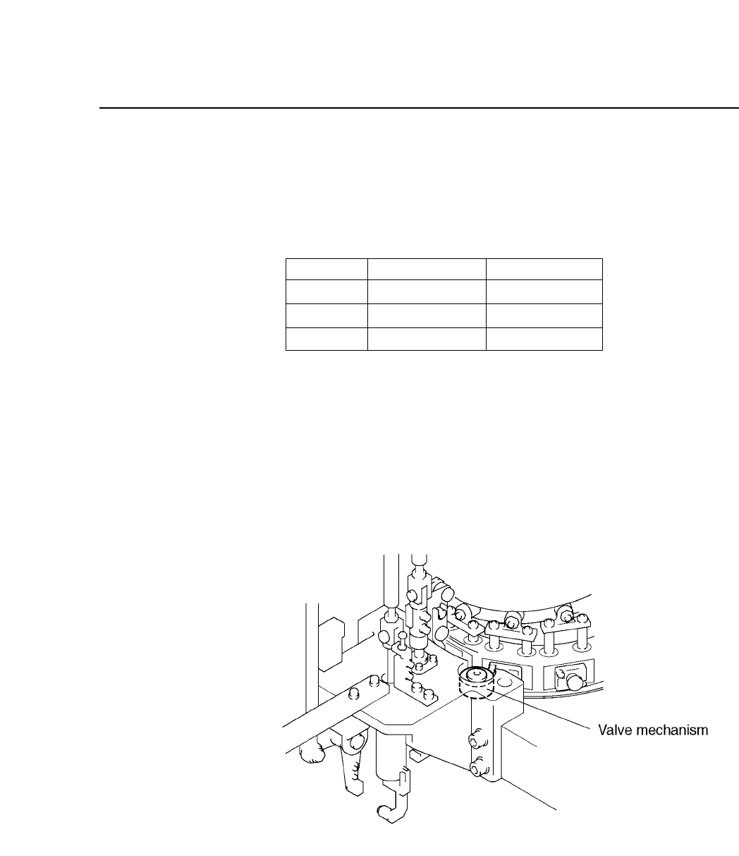
5.12.2Valve Return Mechanism
When the twelve heads are rotated backward manually (with the
handle), a valve mechanism at station 12 forces the spool to return.
Adjustment is not necessary.
Fig. 5-48 Spool Returning Mechanism at Station 12
S
L
M
Green unlit
Green lit
Green lit
Green lit
Green lit
Green unlit
Nozzle Sensor 1
Sensor 2
CP IV-3 Maintenance

Chapter 5 The Twelve Stations
5 – 46
Version 6.0
CP IV-3 Maintenance
6 – 1
Version 7.0
Chapter 6 Placing Heads
6. Placing Heads
The placing head picks parts from the feeders and place them onto the board
currently in production. The placing head assembly consists of the holder,
nozzle, shaft and other related parts.
6.1 How to Remove the Holder
Before removing the holder, the user must do the following four things:
• Move the holder to be removed to station 8.
• Move the XY table away from station 8 by hand. The holder is very
difficult to remove if the XY table is underneath.
• For safety's sake, turn off the power.
• To remove the holder, use a box wrench (MPJ-0072).
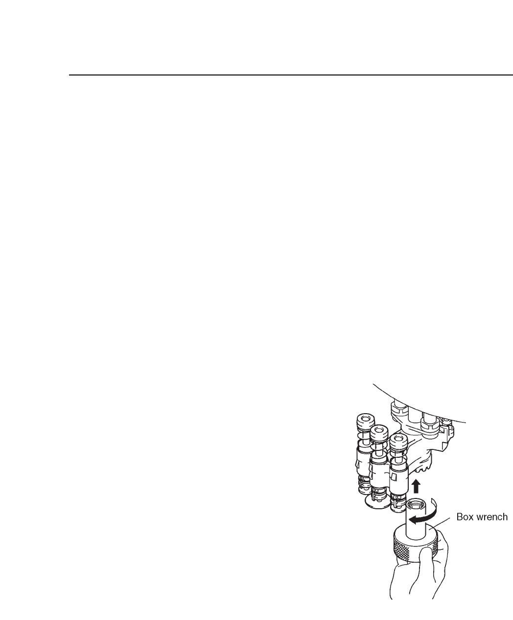
6.1.1 Removal
(1) Use the box wrench to
loosen the M6 hexagonal
nut under the holder.
(2) After removing the nut,
slide the holder down to
remove it. The spring
washer and washer will
also be removed so take
care not to drop them.
Fig. 6-1 Holder Removal
CP IV-3 Maintenance