CP43维护手册.pdf.pdf - 第114页
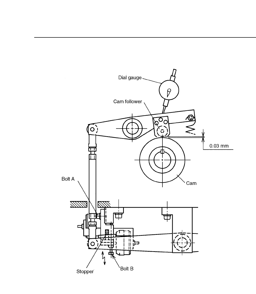
Chapter 10 Cam Box Fig. 10-14 Station 3 Cam Lever Stopper 10 – 14 V ersion 7.0 CP IV -3 Maintenance

10 – 13
Version 7.0
Chapter 10 Cam Box
10.6.2Stations 3, 7 and 11 Cam Lever Stopper Adjustment
Follow these directions to adjust these stoppers.
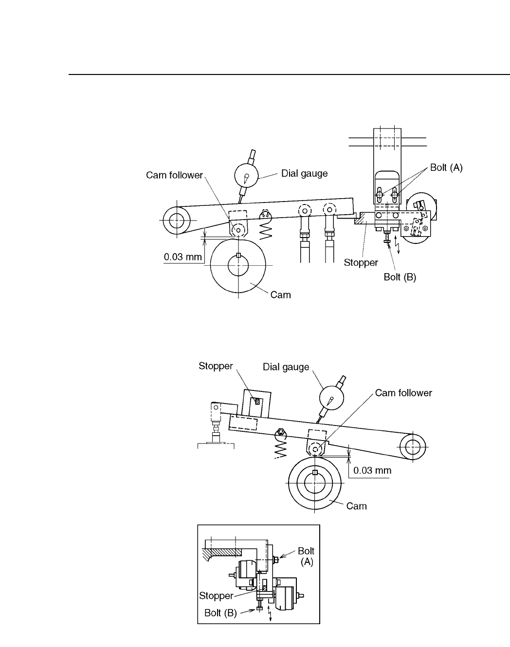
(1) Set the dial gauge on the cam lever near each cam follower as
shown in figures 10-16, 10-17 and 10-18.
(2) With the stoppers not set, turn the handle to the cam stopping
point (around 348° ~ 350°). Record this angle.
Cam stopping point:
3 station 348°
7 station 175°
11 station 348°
(3) Set the dial gauge to zero.
(4) Turn the I/O output on and set the stoppers.
For station 3, use I/O output Y022.
For station 7, use I/O output Y029.
For station 11, use I/O output Y02A.
If the stoppers cannot be set, turn the cam axis a little, but
watch the dial gauge carefully.
(5) Turn the cam handle until the cam follower is held floating by
the stopper. At station 7 only turn the cam handle in the
reverse direction.
For station 3, this is 230° ~ 300°.
For station 7, this is 230° ~ 300°.
For station 11, this is 260° ~ 300°.
(6) Loosen bolt (A).
(7) Watching the cam lever, adjust the stopper positions by turning
bolt (B) so that the lever is 0.03 mm above the stoppers.
(8) After adjustment, confirm that the stopper turns on and off at
the following stations and cam angles.
Station 3 354°-168°
Station 7 175°
Station 11 354-162°
CP IV-3 Maintenance
Chapter 10 Cam Box
Fig. 10-14 Station 3 Cam Lever Stopper
10 – 14
Version 7.0
CP IV-3 Maintenance
10 – 15
Version 7.0
Chapter 10 Cam Box
Fig. 10-15 Station 7 Cam Lever Stopper
Fig. 10-16 Station 11 Cam Lever Stopper
CP IV-3 Maintenance