CP43维护手册.pdf.pdf - 第127页
14 – 1 V ersion 7.0 Chapter 14 Replacing Consumable Parts 14. Replacing Consumable Parts This section describes procedur es for r eplacing consumable parts. 14.1 Nozzle Replacement Replace nozzles that become bent, defor…
Chapter 13 Changeover
13.7Follow-up Pin Changeover (When Changing Pin Diameter)
The procedures for changing the attached pin are the same as when
changing the reference pin, except there is no dog for the attached pin.
13.8Fiducial Mark Settings
When the reference pin and follow-up pins are not used, and the machine
only uses the fiducial marks as a reference, follow the steps listed below.
(1) Select [LOADER], [LOADING POSTN], and press the START button
to move the XY table to the loading position.
(2) Press [LIFTER ▲] and the XY table is raised to the same height as the
in and out conveyors.
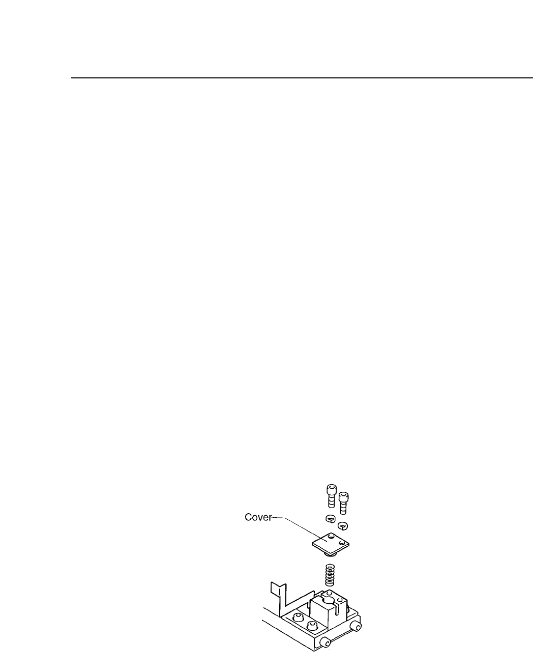
(3) Unscrew the pivot pin.
(4) Unscrew the pin holder set.
(5) Remove the pin and holder from the block. Be careful that the spring
loaded beneath the pin does not shoot out.
(6) While the spring is in the block, attach the cover to the reference pin
block. While the dog is attached, check to see if the spring pint that is
attached to the cover, is in the hole of the dog. Attach the cover.
(7) It is not necessary to remove the follow-up pin. The block should be
set for each board to be produced.
Fig. 13-3 Fiducial Mark Reference
13 – 4
Version 7.0
CP IV-3 Maintenance

14 – 1
Version 7.0
Chapter 14 Replacing Consumable Parts
14.Replacing Consumable Parts
This section describes procedures for replacing consumable parts.
14.1Nozzle Replacement
Replace nozzles that become bent, deformed, or blocked. When removing
the damaged nozzle, be careful not to lose the spring loaded under it.
Caution: When removing the nozzle, do not hold the nozzle assembly close to
the eye. The tension of the spring will shoot the nozzle out with
enough force to hit and injure the eye.
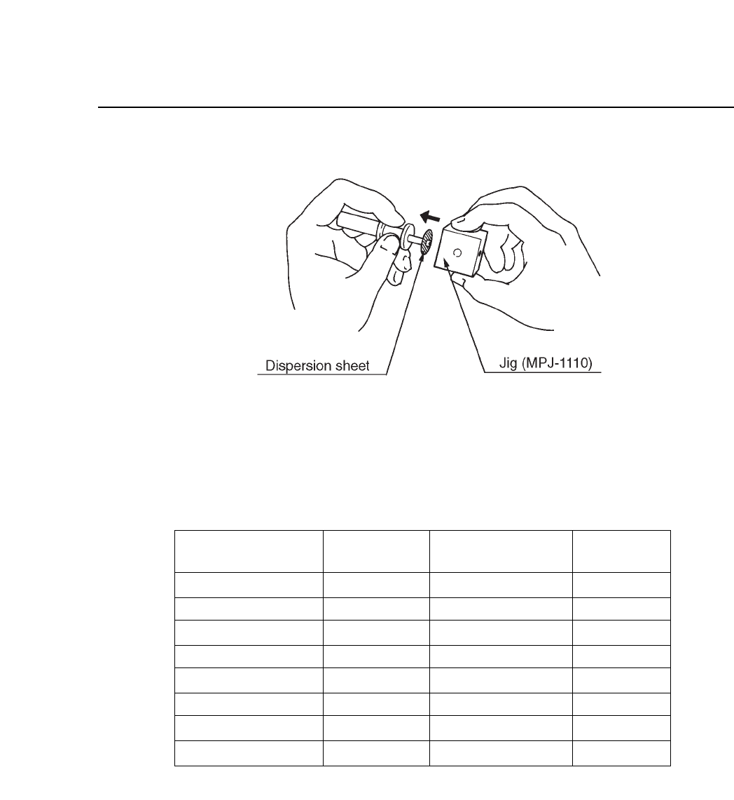
14.2Nozzle Dispersion Seal Replacement
Replace dirtied nozzle dispersion seals that cause vision processing errors.
To change seals, use jig MPJ-1110. This jig can be used on nozzles with a
diameter of ø0.7, ø1.0, ø1.3, ø2.5, ø3.7 or ø5.0.
(1) Always wash your hands before handling the seals.
(2) Choose the correct seal, referring to table 14-1 for help.
(3) Check that the fluorescent seal is free of deformity and is clean.
(4) Peel the fluorescent seal from its paper backing and remove the small
circular cutout at the center of the seal by pushing it out from the side
of the seal covered with fluorescent paint. If the cutout is pushed out
from the side covered with adhesive, some of the fluorescent paint
may be torn away when the circular cutout comes loose from the rest
of the seal.
(5) Match the center of the seal with the center of the nozzle. Using jig
MPJ-1110, push the seal into the nozzle as shown in figure 14-1 on the
next page. Check that no space exists between the seal and the nozzle.
(6) Use an exacto knife to cut away any excess fluorescent seal.
(7) Clean the fluorescent seal with a soft brush.
CP IV-3 Maintenance
Chapter 14 Replacing Consumable Parts
Fig. 14-1 Nozzle Seal Replacement
Table 14-1 Nozzles and Fluorescent Seal Numbers
ø0.7 S nozzle
ø1.0 S nozzle
ø1.3 S, M nozzles
ø1.8 M nozzle
ø2.5 M nozzle
ø2.5 L nozzle
ø3.7 L nozzle
ø5.0 L nozzle
Nozzle Size
Nozzle Assy
Number
Fluorescent
Seal
AMPH-8211
AMPH-8221
AMPH-8231
AMPH-8241
AMPH-8251
AMPH-8261
AMPH-8271
AMPH-8281
12
12
12
12
12
25
25
25
LPH-5010
LPH-5020
LPH-5030
LPH-5040
LPH-5050
MPH-3011
MPH-3021
MPH-3031
Diameter of
Luminescent Area
14 – 2
Version 7.0
CP IV-3 Maintenance