CP43维护手册.pdf.pdf - 第92页
Chapter 6 Placing Heads 6.3 Nozzle Categories The nozzle sizes listed below must be used with the parts as listed. S Nozzle ø0.7 1005C/R, 1608 C/R, Super minimold TR S Nozzle: ø1.0 1608 C/R, 2125 C/R, 3216 C/R S Nozzle ø…
6 – 3
Version 7.0
Chapter 6 Placing Heads
6.2 How to Remove the Nozzle
When removing the nozzle, use nozzle removal jig MPJ-1100.
6.2.1 Removal
To remove the nozzle from the holder, follow the steps below.
These steps require the nozzle removal jig MPJ-1100.
(1) Rotate the nozzle by hand to a point where the nozzle catch is
facing the front.
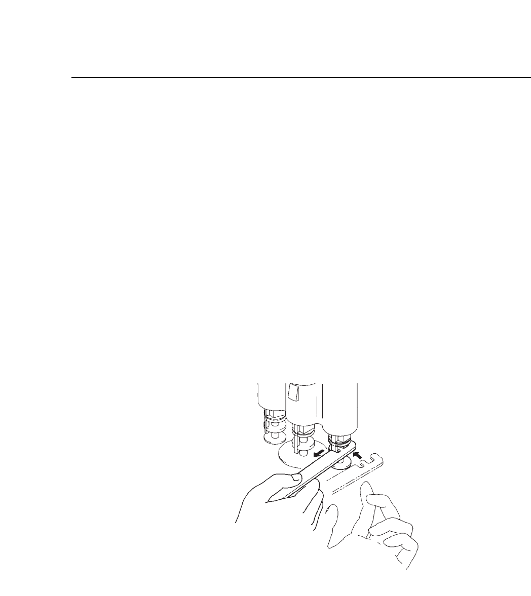
(2) Set the nozzle removal jig, MPJ-1000, on the nozzle stem, as
shown in figure 6-3, and pull toward yourself. This disengages
the nozzle catch, allowing the nozzle to be slid out of the
holder.
Note: One hand should be placed under the nozzle to prevent damage in
case it shoots out.
Fig. 6-3 Nozzle Removal
6.2.2 Attachment
A nozzle is attached simply by inserting the upper step into the
holder and sliding it upward.
CP IV-3 Maintenance

Chapter 6 Placing Heads
6.3 Nozzle Categories
The nozzle sizes listed below must be used with the parts as listed.
S Nozzle ø0.7 1005C/R, 1608 C/R, Super minimold TR
S Nozzle: ø1.0 1608 C/R, 2125 C/R, 3216 C/R
S Nozzle ø1.3 2125 C/R, 33216 C/R, Minimold TR, Tantalum A
M Nozzle ø1.3 2125 C/R, 3216 C/R, Minimold TR, Tantalum A
M Nozzle ø1.8 Tantalum A/B, 3216 C/R, power transistors,
filters, diodes, aluminum electrolytic capacitors
M Nozzle ø2.5 Tantalum B/C/D, power transistors, filters,
aluminum electrolytic capacitors, SOIC 8 ~16,
SSOP 20
L Nozzle ø2.5 SOIC 20, SSOP 24~30, SQFP 48
L Nozzle ø3.7 Tantalum D, SOIC 20~28W, PLCC 18~32,
SSOP 16~30, SQFP 48, SOJ 26
L Nozzle ø5.0 SOIC 20~28W, PLCC 18~32, SSOP 24~30,
SQFP 48, SOJ 26
Note: Nozzle sizes ø7.0 and ø10.0 are only used on the CP-V.
6 – 4
Version 7.0
CP IV-3 Maintenance

Chapter 7 The Device Tables
7. The Device Tables
The term “device” refers to the location of a tape feeder.
The tape feeders are set up on the device table in the arrangement the program
specifies. During production the D-axis tables move the tape feeders directly
under station 1 in the order specified by the program. Afterwards, the nozzle
from station 1 lowers and picks up the part.
The two D-axis tables can operate in the following three modes:
• Device change mode
When the parts run out on one table, the other table is automatically
selected.
• Changeover mode
Only one table operates at a time. The other table is automatically selected
at the end of the current production program.
• Joint mode
The two tables with 80 devices each are joined to make one table with 160
devices.
For the CP IV and CP IV-2, the two device tables are linked by a mechanism
called the slider.
The device tables on the CP IV-3 each have their own motor and can work
independently of the other. In the joint mode, the two device tables are used
together during production.
7.1 Device Table Configuration
The slider and its principal parts are shown on the following page.
7 – 1Version 7.0
CP IV-3 Maintenance