CP43维护手册.pdf.pdf - 第119页
12 – 1 V ersion 7.0 Chapter 12 VME Boards 12. VME Boards This chapter describes the control boar ds used with the CP IV -3. As shown in the illustration below , the control boar ds ar e in the VME rack in the control box…
Chapter 11 Servo Amplifiers
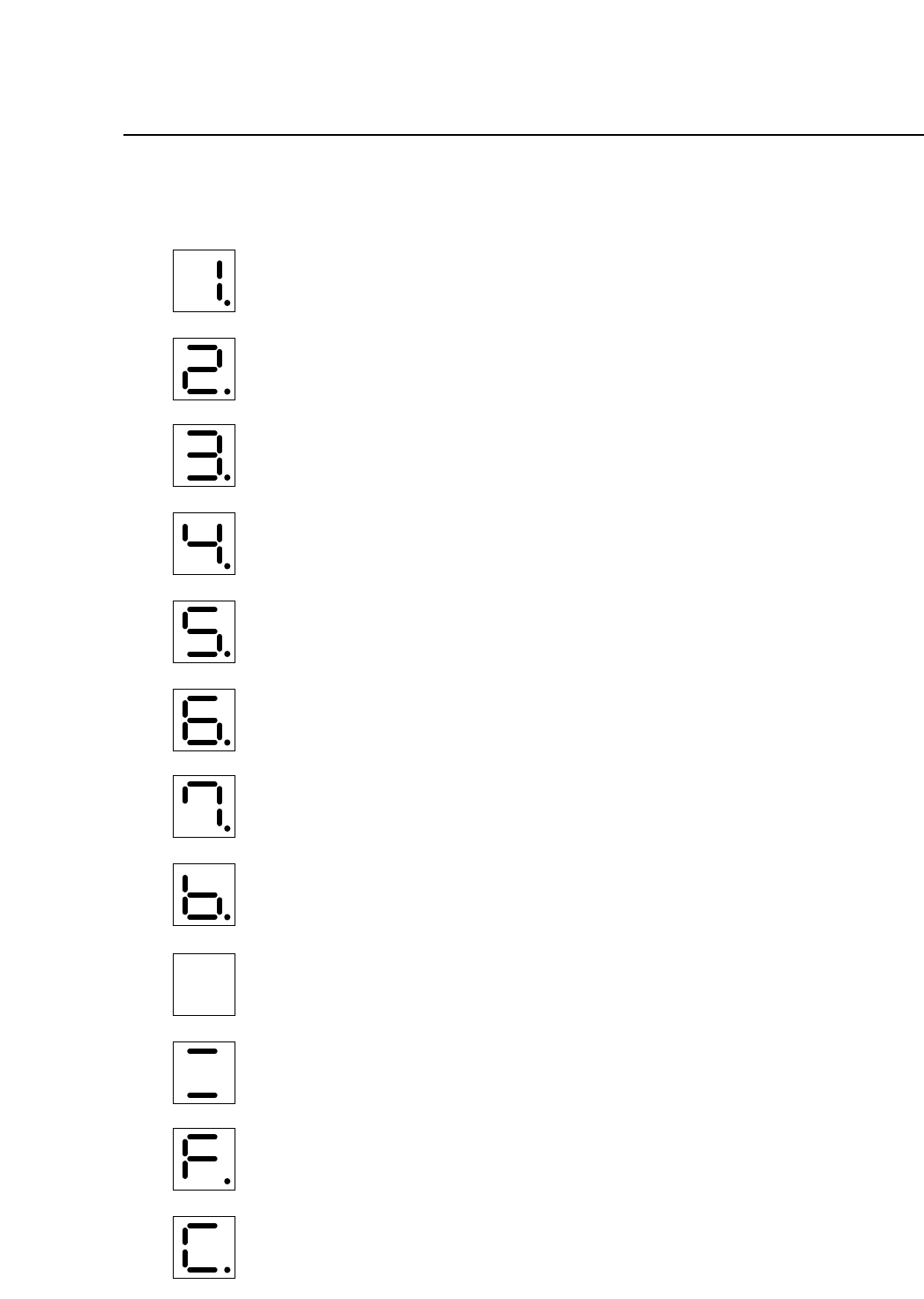
11.2Display During Servo Amp Malfunction
Over-current (all axes)
Circuit protector tripped (all axes)
Regenerative trouble (all axes)
Over-voltage (all axes)
Over-speed (all axes)
Voltage drop (all axes)
Overload (all axes)
A/D error (all axes)
CPU error (this display is for Fθ, cam, D, X, Y axes)
CPU error (this display is for Z axis)
Open phase (no display for Z axis)
Overrun protection (all axes)
11 – 2
Version 7.0
CP IV-3 Maintenance
12 – 1
Version 7.0
Chapter 12 VME Boards
12.VME Boards
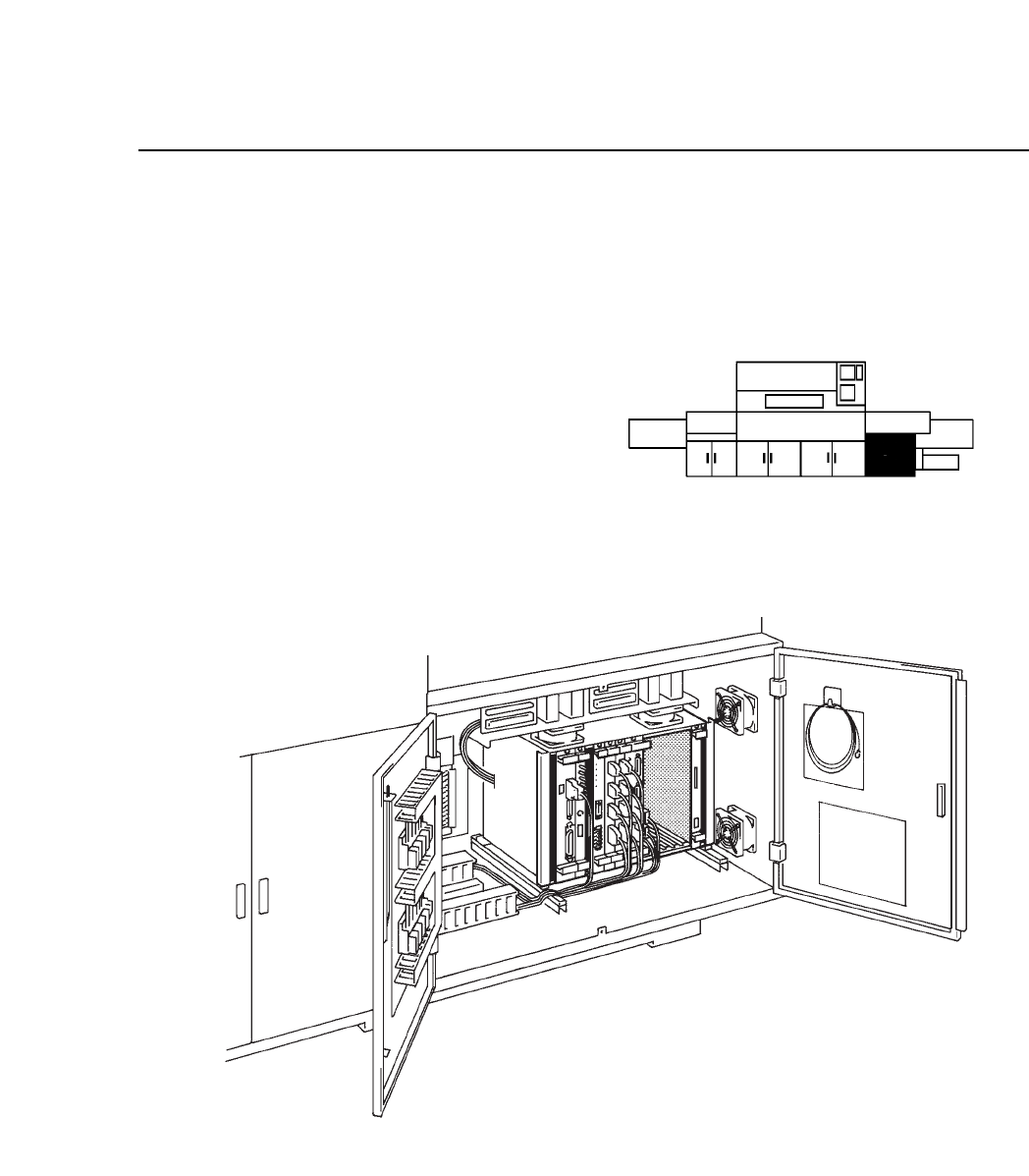
This chapter describes the control boards used with the CP IV-3.
As shown in the illustration below,
the control boards are in the VME
rack in the control box on the lower
right-hand side of the machine.
Fig. 12-1 Control Box Location and Detailed View
CP IV-3 Maintenance
Chapter 12 VME Boards
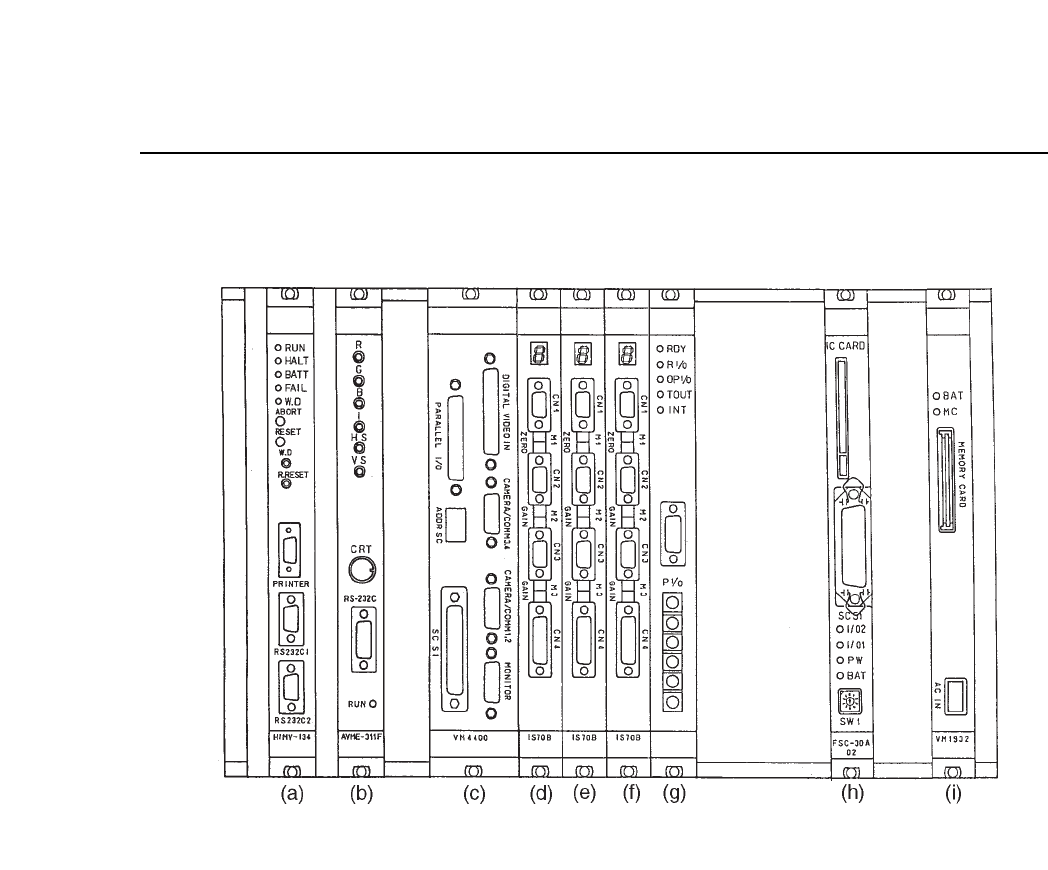
Fig. 12-2 VME Rack
The functions of the VME boards are described below.
(a) CPU board HIMV-134
This board is the center of the machine control system. It carries out all the
processing required to operate the machine. Proper data and Program data
stored in the RAM, and MCS communication come in through the serial
port here. Under normal conditions, the "RUN" LED is lit.
Note: When removing the board from the rack, perform reset start.
12 – 2
Version 7.0
CP IV-3 Maintenance