CP43维护手册.pdf.pdf - 第53页
5 – 11 V ersion 6.0 Chapter 5 The T welve Stations • Adjustment Method Have the adjustment jig and gage prepar ed befor ehand. 1) Set the adjustment jig at D1 on the device table. • Ensure that ther e are no obstr uction…
Chapter 5 The Twelve Stations
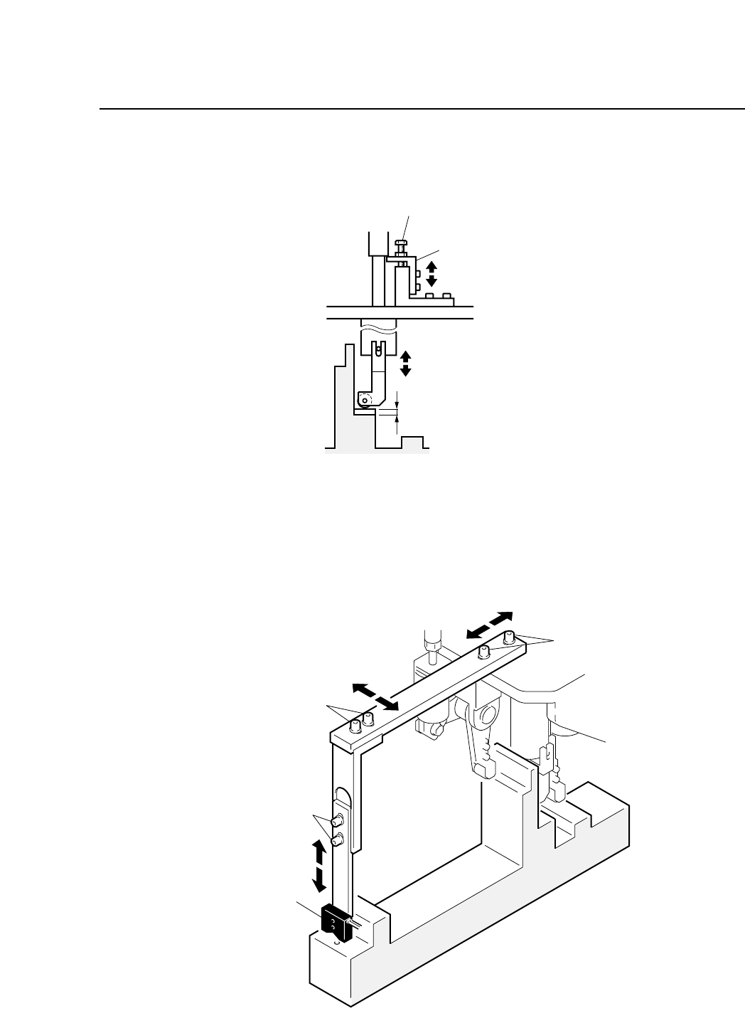
6) It is also possible to perform fine adjustment at the cam angle
262° with the stopper bolt.
Fig. 5-9 Station 1 Part Lifter Stopper Adjustment
5.1.4 Tape End Detection
Tape-end detection uses a reflective type sensor that checks for the
end of the tape and notifies the operator before the end of the tape.
Fig. 5-10 Station 1 Tape End Sensor
Adjusting bolt A
Adjusting bolt B
Adjusting bolt C
Sensor
Stopper bolt
Fine Adjustment Stopper
Clearance C = Gage thickness
5 – 10
Version 6.0
CP IV-3 Maintenance
5 – 11
Version 6.0
Chapter 5 The Twelve Stations
• Adjustment Method
Have the adjustment jig and gage prepared beforehand.
1) Set the adjustment jig at D1 on the device table.
• Ensure that there are no obstructions on the base of the jig.
• Confirm that the jig will not interfere with station 1.
Note: It is possible to make adjustments with the jig set at positions
other than D1.
2) Press [SET] → [POSITION] → [D AXIS] → (input device # 1) →
[CR] and [START] to move the adjustment jig to station 1.
3) Press the EMERGENCY STOP button to take the machine from
200 volts down to 100 volts.
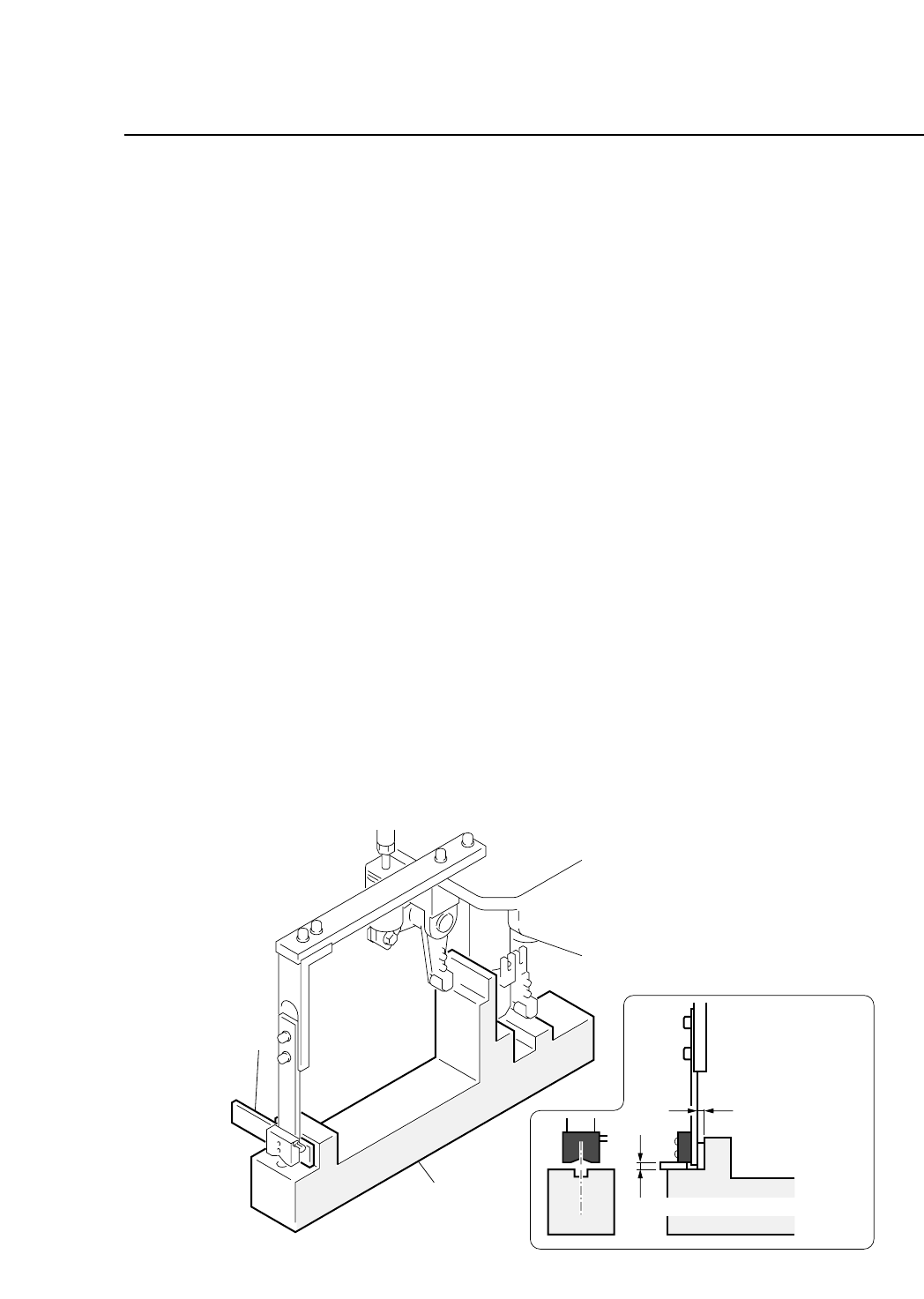
4) Adjust the from and back position of the sensor.
• Insert the gage into gap D, and loosen bolt A to eliminate any
clearance.
5) Adjust the vertical position of the sensor.
• Insert the gage into gap E, loosen bolt C, and eliminate any
clearance.
6) Adjust the horizontal position of the sensor.
• Loosen bolt B to align the center of the sensor to the center of
the hole in the jig.
Fig. 5-11 Station 1 Tape End Sensor Adjustment
Gage
Adjustment jig
Clearance D
= Gage thickness
Clearance E = Gage thickness
CP IV-3 Maintenance
Chapter 5 The Twelve Stations
• Sensitivity Adjustment
1) Set an 8W x 4P paper tape feeder on the device table and move
it to station 1.
2) Press the EMERGENCY STOP button to take the machine from
200 volts down to 100 volts.
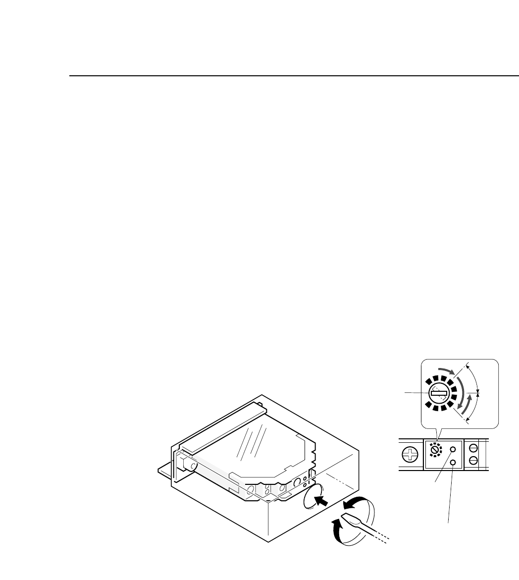
3) Turn the sensitivity trimmer volume to zero. Slowly turn the
trimmer to the right to a position where green LED goes on
(position A).
4) Remove the paper tape from the feeder. The green LED will go
off.
5) Adjust the trimmer volume to the right to the position where
the green LED goes on (position B).
6) Set the trimmer volume between position A and position B.
7) Ensure that the sensor actually detects the end of the tape.
Fig. 5-12 Station 1 Tape End Sensor Volume Adjustment
Sensitivity adjustment
trimmer
Green LED
Red LED
SET
A
B
"
"
5 – 12
Version 6.0
CP IV-3 Maintenance