CP43维护手册.pdf.pdf - 第54页
Chapter 5 The T welve Stations • Sensitivity Adjustment 1) Set an 8W x 4P paper tape feeder on the device table and move it to station 1. 2) Press the EMERGENCY ST OP button to take the machine fr om 200 volts down to 10…
5 – 11
Version 6.0
Chapter 5 The Twelve Stations
• Adjustment Method
Have the adjustment jig and gage prepared beforehand.
1) Set the adjustment jig at D1 on the device table.
• Ensure that there are no obstructions on the base of the jig.
• Confirm that the jig will not interfere with station 1.
Note: It is possible to make adjustments with the jig set at positions
other than D1.
2) Press [SET] → [POSITION] → [D AXIS] → (input device # 1) →
[CR] and [START] to move the adjustment jig to station 1.
3) Press the EMERGENCY STOP button to take the machine from
200 volts down to 100 volts.
4) Adjust the from and back position of the sensor.
• Insert the gage into gap D, and loosen bolt A to eliminate any
clearance.
5) Adjust the vertical position of the sensor.
• Insert the gage into gap E, loosen bolt C, and eliminate any
clearance.
6) Adjust the horizontal position of the sensor.
• Loosen bolt B to align the center of the sensor to the center of
the hole in the jig.
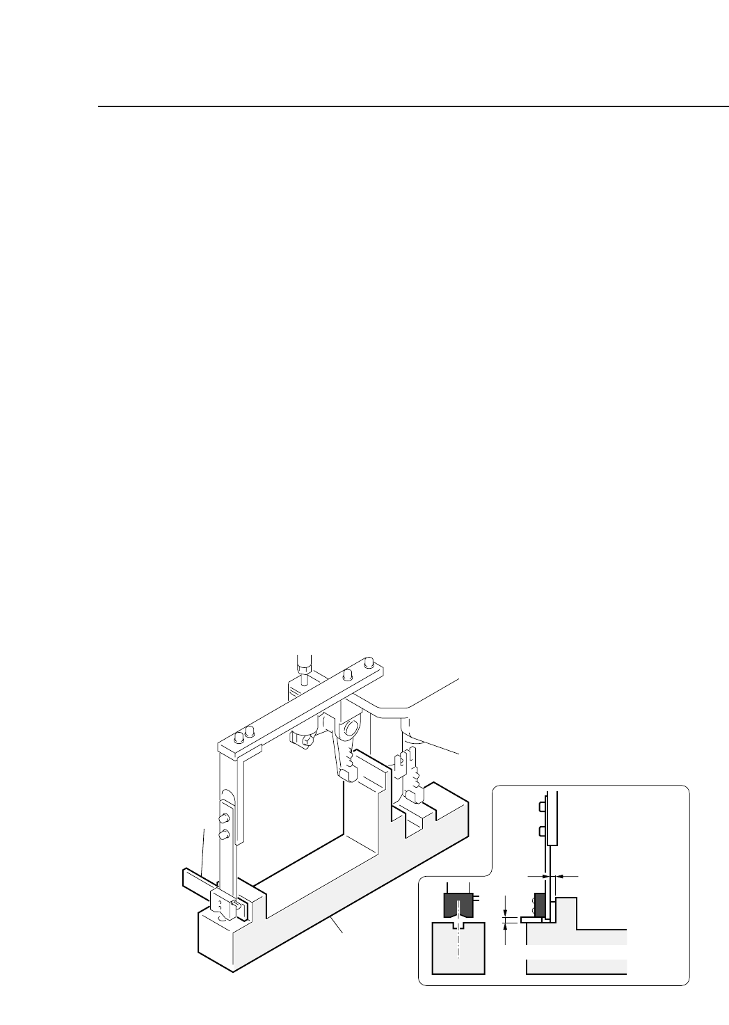
Fig. 5-11 Station 1 Tape End Sensor Adjustment
Gage
Adjustment jig
Clearance D
= Gage thickness
Clearance E = Gage thickness
CP IV-3 Maintenance
Chapter 5 The Twelve Stations
• Sensitivity Adjustment
1) Set an 8W x 4P paper tape feeder on the device table and move
it to station 1.
2) Press the EMERGENCY STOP button to take the machine from
200 volts down to 100 volts.
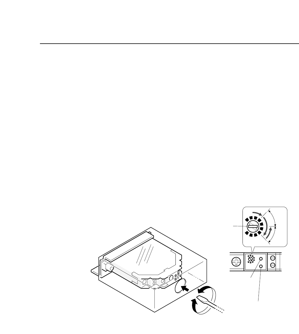
3) Turn the sensitivity trimmer volume to zero. Slowly turn the
trimmer to the right to a position where green LED goes on
(position A).
4) Remove the paper tape from the feeder. The green LED will go
off.
5) Adjust the trimmer volume to the right to the position where
the green LED goes on (position B).
6) Set the trimmer volume between position A and position B.
7) Ensure that the sensor actually detects the end of the tape.
Fig. 5-12 Station 1 Tape End Sensor Volume Adjustment
Sensitivity adjustment
trimmer
Green LED
Red LED
SET
A
B
"
"
5 – 12
Version 6.0
CP IV-3 Maintenance
5 – 13
Version 6.0
Chapter 5 The Twelve Stations
5.1.5 Cutting Waste Tape
After parts have been picked out of the tape, the empty “waste”
tape is cut off. Waste tape that has been cut is collected by a
vacuum at the back of the machine.
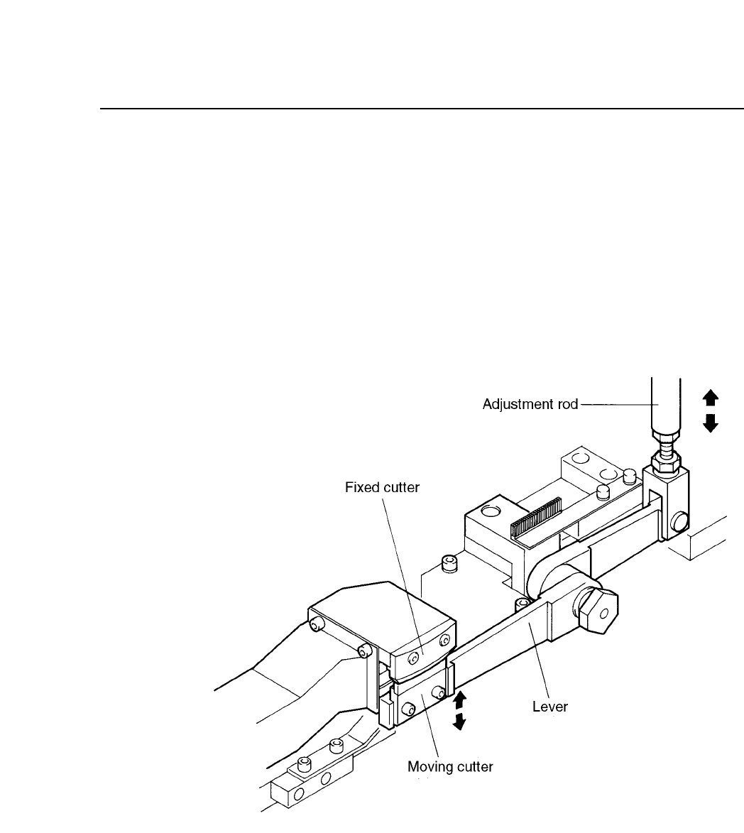
The waste tape cutting operation is driven by a cam mechanism.
The cam drives a lever, which drives a rod, which drives a lever,
which drives the cutter.
The stroke of the rod is a fixed value determined by the curve of the
cam.
Fig. 5-13 Waste Tape Cutting Mechanism
CP IV-3 Maintenance