CP43维护手册.pdf.pdf - 第120页
Chapter 12 VME Boards Fig. 12-2 VME Rack The functions of the VME boards ar e described below . (a) CPU board HIMV -134 This board is the center of the machine contr ol system. It carries out all the processing r equir e…
12 – 1
Version 7.0
Chapter 12 VME Boards
12.VME Boards
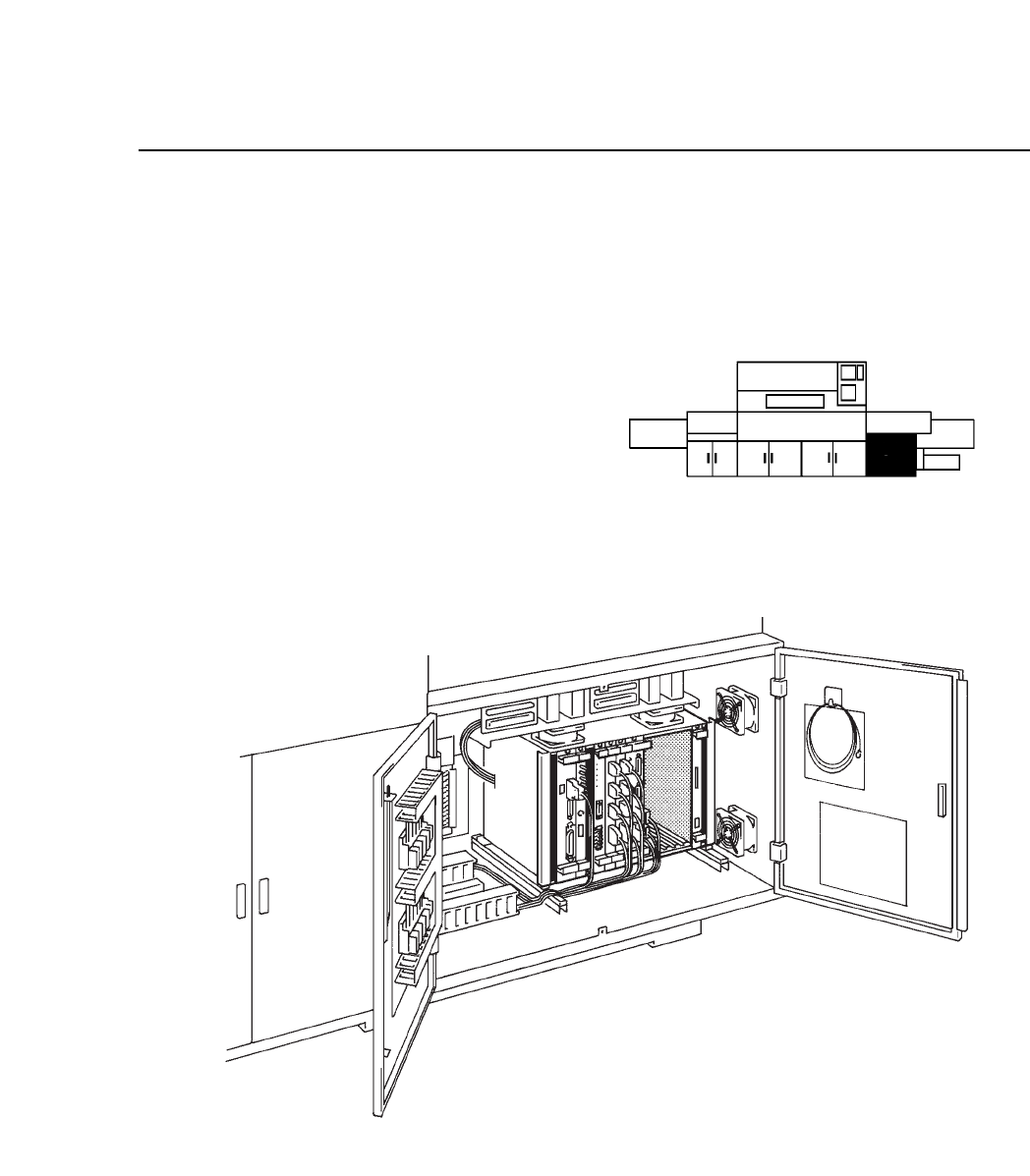
This chapter describes the control boards used with the CP IV-3.
As shown in the illustration below,
the control boards are in the VME
rack in the control box on the lower
right-hand side of the machine.
Fig. 12-1 Control Box Location and Detailed View
CP IV-3 Maintenance
Chapter 12 VME Boards
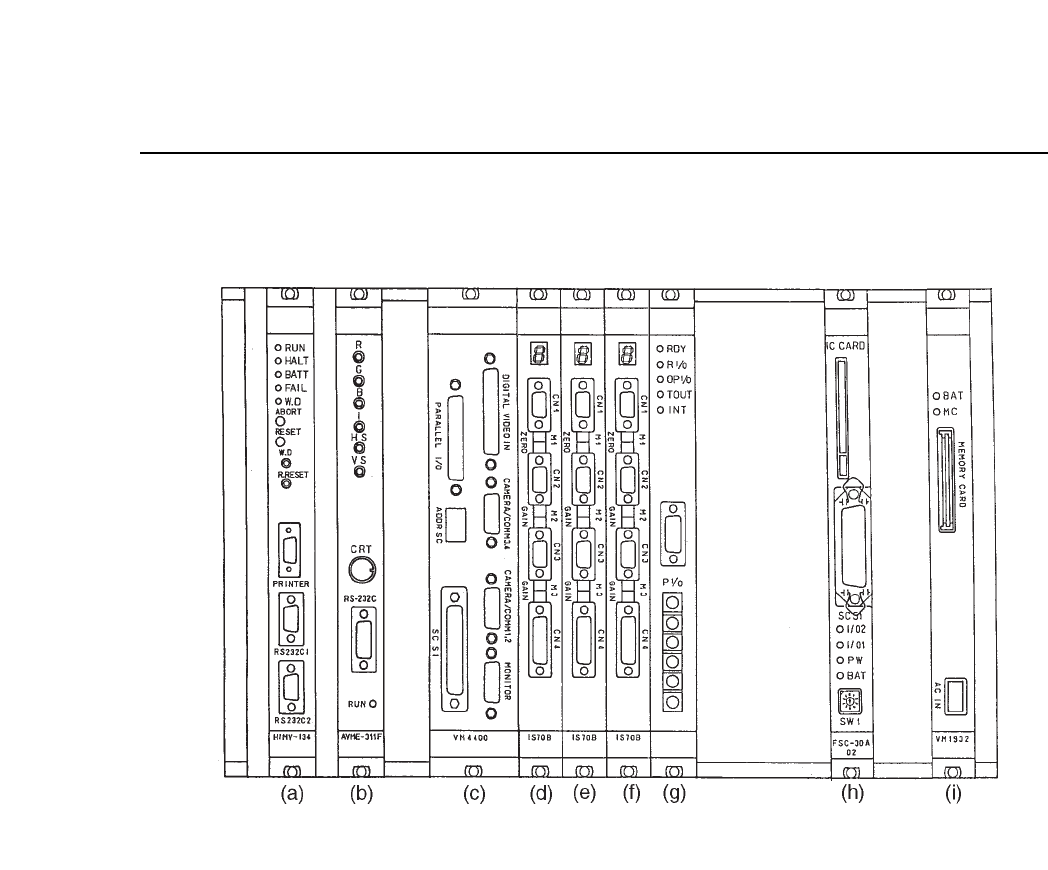
Fig. 12-2 VME Rack
The functions of the VME boards are described below.
(a) CPU board HIMV-134
This board is the center of the machine control system. It carries out all the
processing required to operate the machine. Proper data and Program data
stored in the RAM, and MCS communication come in through the serial
port here. Under normal conditions, the "RUN" LED is lit.
Note: When removing the board from the rack, perform reset start.
12 – 2
Version 7.0
CP IV-3 Maintenance

12 – 3
Version 7.0
Chapter 12 VME Boards
(b) Console board AVME ~ 311F
This board controls the color display on the operation panel.
(c) Vision processing board VM4400
This board controls vision processing of parts that are inspected before
placement.
(d) Servo board IS70B
This board controls the servo motors for the machine axes. The speed and
positioning of the C and Fθ axes are controlled with this board.
(e) Servo board IS70B
This board controls the servo motors for the machine axes. The speed and
positioning of the X, Y, and Z axes are controlled with this board.
(f) Servo board IS70B
This board controls the servo motors for the machine axes. The speed and
positioning of the D1 and D2 axes are controlled with this board.
(g) VME interface board MX100CP91D
This board transmits signals from sensors and switches to the CPU and
uses signals from the CPU to control the relay valve, etc. This board has a
direct cable to the I/O in control box 1.
(h) SCSI Vision Processing External Memory Board
FSC-30A02 and FSC-30C
This board contains necessary data pertaining to nozzles and picking parts.
This memory is saved to the board and backed up by a battery so turning
the machine on or off, or performing reset start will not have any effect on
this memory.
(i) MP board VM1932
This board is connected to a battery which serves as a backup to preserve
the RAM memory when the machine power is cut. If this battery goes dead
and the machine power is cut the memory will be erased.
When the machine control system comes with a memory card, the card
must be inserted here.
This board goes into the the farthest right slot of the board rack.
Note: For further information on changing the memory card see Chapter 16,
Upgrading the Software.
CP IV-3 Maintenance