CP43维护手册.pdf.pdf - 第25页
Chapter 2 Setting Up the CP IV -3 2.3 Air Supply Fix a socket to the end of the air supply hose and connect the socket to the air connector plug on the machine. T urn the air inlet handle until the filter regulator r ead…
Chapter 2 Setting Up the CP IV-3
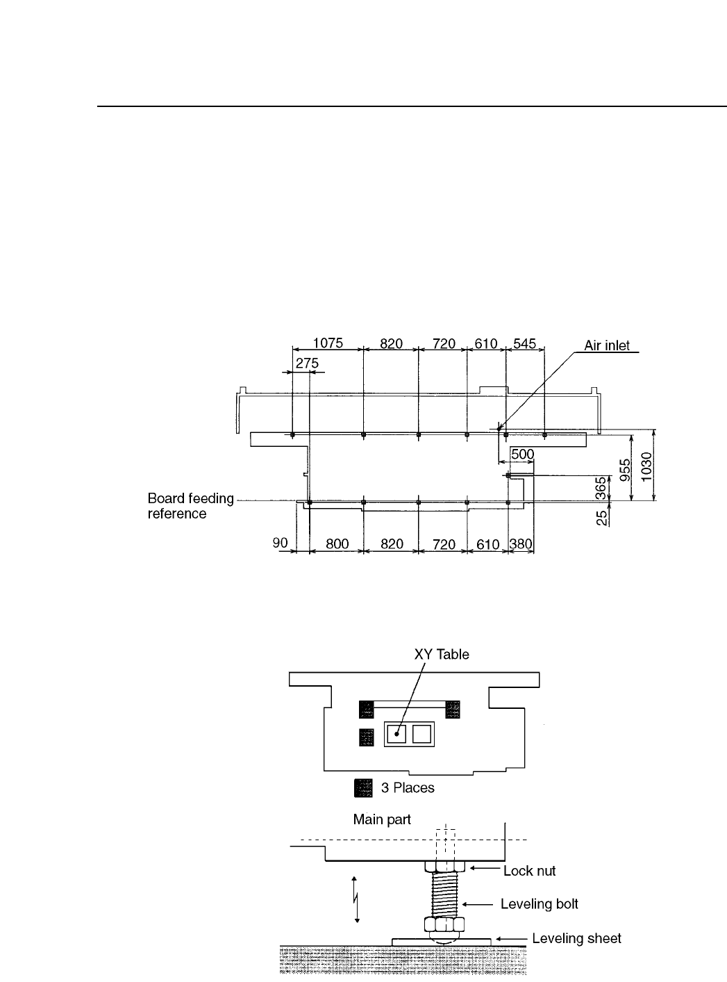
2.2 Leveling
Place the machine on leveling sheets and adjust so that the machine is
level to the ground. If the machine is not level, placing accuracy will be
adversely affected. To level the machine, place a spirit level on the
unpainted portion of the main body of the machine (figure 2-3) and adjust
the leveling bolts while repeatedly checking the reading on the level.
Fig. 2-2 Position of Machine Leveling Sheets
Fig. 2-3 Spirit Level Placement Positions and Detailed View of Leveling
Bolts
2 – 2
Version 4.0
Chapter 2 Setting Up the CP IV-3
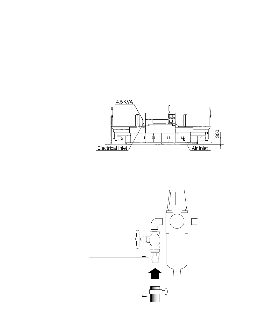
2.3 Air Supply
Fix a socket to the end of the air supply hose and connect the socket to the
air connector plug on the machine. Turn the air inlet handle until the filter
regulator reads 5 kg/cm
2
. Refer to figures 2-4 and 2-5 for more details.
Fig. 2-4 Air Inlet
Fig. 2-5 Detailed View of Air Inlet
Nipple
Hose (Inside
diameter 8 mm)
Note: Fuji does not supply the hose.
Air pressure at least 5 kg/cm
2
2 – 3
Version 8.0
2.4 Electric Power Supply
• Power Consumption
The CP IV-3 uses approximately 4.5 KVA. Connect the machine to a
power supply with a capacity of at least 4.5 KVA.
• Power Supply Cable
Use an appropriate power supply cable.
• Voltage
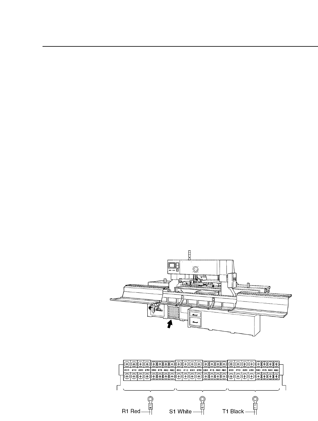
The CP IV-3 contains a multiple input transformer which allows the
machine to be used with the normal supply voltage in any country.
The location of this transformer is shown below. Before connecting
the power supply to the machine, make sure that the transformer tap
position matches the actual voltage to be supplied to the machine.
(The transformer is normally set correctly for the destination country
before the machine is shipped from the Fuji factory.)
• Location of Power Supply Connector
Connect the primary power supply cable to the circuit breaker located
on the left side of the machine.
Fig. 2-6 Position of the Transformer and Transformer Taps
2 – 4
Chapter 2 Setting Up the CP IV-3
Version 8.0