雅马哈YSM切刀更换和保养方法..pdf - 第13页
Service Engineer Service Information SI0907002E - 003 = YS machine’s tape cu tter cleaning and lubrication 13 / 63 3.3 Preparation for ensurin g safety See “ 1.4 Use the Lock -out padlock ” for the details. 1. Turn OFF t…

Service Engineer
Service Information
SI0907002E-003=YS machine’s tape cutter cleaning and lubrication
12/63

Service Engineer
Service Information
SI0907002E-003=YS machine’s tape cutter cleaning and lubrication
13/63
3.3 Preparation for ensuring safety
See “1.4 Use the Lock-out padlock” for the details.
1. Turn OFF the air supply and power of the machine.
Power OFF the machine and turn the Air supply supply/shut off switch clockwise to stop the air
supply to the machine.
2. Put the padlock to the keyhole for lock out of the Air supply supply/shut off valve.
3. Remove the air hose just in case.
Caution:
The location and the shape of the keyhole for the lock out padlock and the valve vary depending
on the model.
Make sure to check the location before the work.
4. Turn the Air supply supply/shut off valve for the tape cutter clockwise and release the
residual air.
Turn OFF the light blue coloured Air supply supply/shut off valve for the tape cutter and release the
residual air.
Caution:
Release the residual air inside the air hose for the tape cutter in order to free the tape cutter blade.
Service Engineer
Service Information
SI0907002E-003=YS machine’s tape cutter cleaning and lubrication
14/63
3.4 Remove the Fixed feeder bank
There are four (4) type of fixed feeder banks – Fixed feeder bank with 60 feeder positions, with 32
feeder positions, with 24 feeder positions and with 14 feeder positions.
The work procedures for the Fixed feeder bank with 24 feeder positions and the Fixed feeder bank
with 14 feeder positions are almost the same.
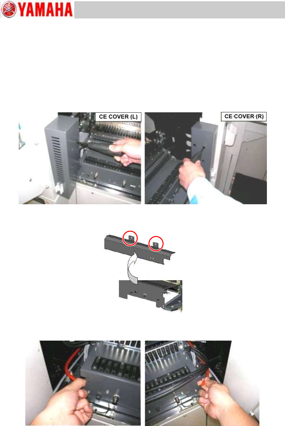
3.4.1 Remove the Fixed feeder bank with 60 feeder positions
Step 1 Remove the right and left safety CE covers.
Figure 8
Step 2 Remove the cover of the tape cutter driving valve.
Figure 9
Step 3 Disconnect the air hoses of the feeder bank at each quick joint.
Figure 10