雅马哈YSM切刀更换和保养方法..pdf - 第57页
Service Engineer Service Information SI0907002E - 003 = YS machine’s tape cu tter cleaning and lubrication 57 / 63 Move the sATS II back to its origina l position.
Service Engineer
Service Information
SI0907002E-003=YS machine’s tape cutter cleaning and lubrication
56/63
3.6 Reinstall the tape guide slope and the feeder bank
Step 1 Before reinstalling the feeder bank, clean and lubricate its surfaces where they come
into contact with the machine.
Use anti-rust spray grease for lubrication. If you do not have the spray grease, apply NSL
grease to the mounting surface with a brush.
Warning:
Never apply grease to the mounting surface with your finger, as it is dangerous.
Step 2 Reinstall the tape guide slope and the feeder bank onto the machine.
The installing procedures vary depending on the type of the feeder bank/feeder exchange
carriage. Install them in the reverse order of removing them referring to the relevant sections
in this manual.
Tips:
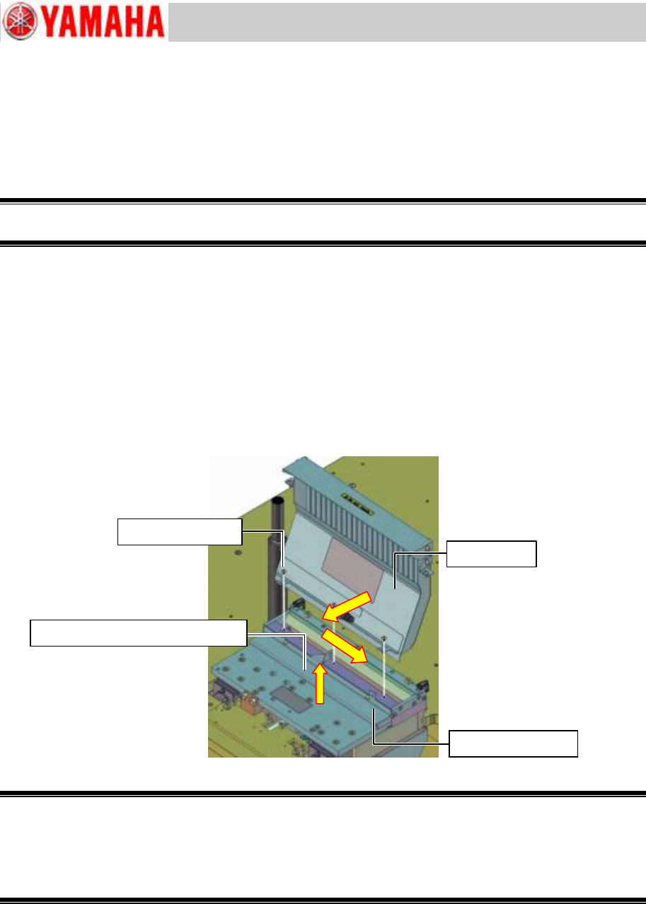
1. Fix the slope cover while pressing it against the near side and the right side (For all the
feeder bank models. See the yellow arrows in the figure below).
2. Fix the chip component anti-drop cover while slightly lifting it up to prevent the cover from
interfering with the lower cutter blade.
Figure 70
Warning:
As all the feeder banks except for the feeder bank with 14 feeder positions weigh over 15 kg.
To ensure safety, be sure that two persons work together to lift up and reassemble the feeder bank.
Also when reassembling the feeder bank, be careful not to let harnesses or air tubes get caught
between the adjoining parts, and ensure that the harnesses and the air hoses are reconnected
properly.
For YS100 and YS88 machines equipped with an sATS
Reinstall the sATS to the machine referring to Service Information “SI0911001E = How to
install the sATS/dYTF for YS100, YS88, YG100R and YG88R machines”.
For YS24X machines equipped with an sATSII
Screw (3 locations)
Slope cover
Chip component anti-drop cover
Screw (2 locations)

Service Engineer
Service Information
SI0907002E-003=YS machine’s tape cutter cleaning and lubrication
57/63
Move the sATSII back to its original position.
Service Engineer
Service Information
SI0907002E-003=YS machine’s tape cutter cleaning and lubrication
58/63
3.7 Check the tape cutter operation
Step 1 Check the condition of the reassembled parts and fully tighten their screws.
Step 2 Attach the removed CE safety covers.
Make sure to attach the CE safety covers on the both sides of the feeder bank.
Caution:
Do not start the machine without installing the CE safety covers to the machine. The machine operator
and/or bystanders may get injured. Also emergency stop status cannot be cancelled depending on the
machine.
Step 3 Make sure that no tools or parts are left inside the machine.
Step 4 Unlock the padlock on the air supply/shut-off switch. Turn ON the air supply to the
machine.
Make sure that no air leakage is observed and air is supplied to the feeder banks and their
tape cutter properly.
Step 5 Power ON and start the machine.
Step 6 Check the tape cutter operation manually by selecting the [Unit] button
[Feeder] tab
[Cutter] button.
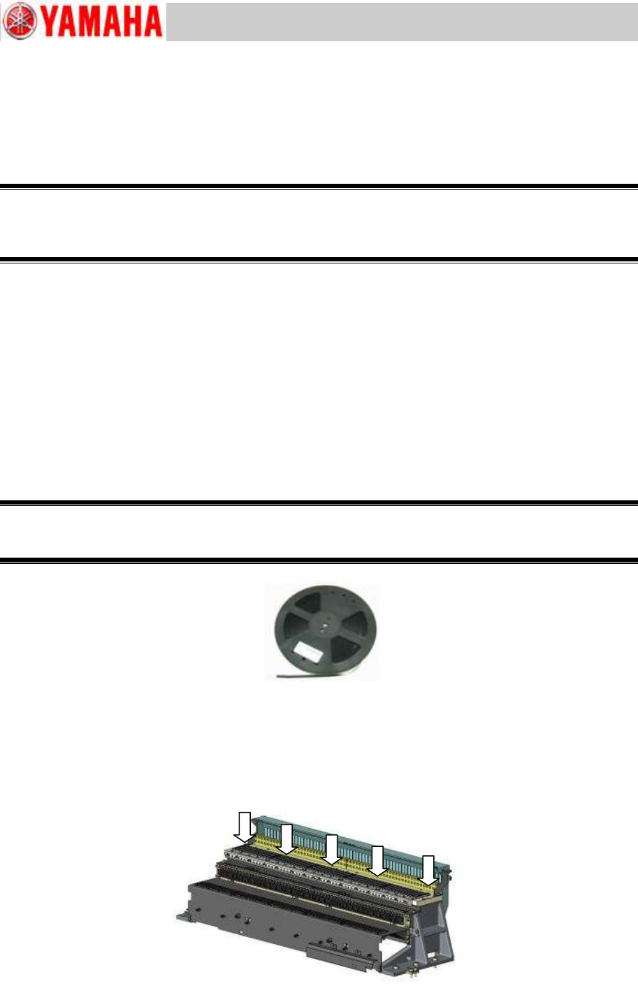
Step 7 Check the tape cutter performance.
Use the test emboss tape for tape cutter performance (Thickness: 0.18mm) for the check.
Important:
Make sure to use the test emboss tape for tape cutter performance (TEST TAPE, CUTTER / KLW-M8825-00).
If you cannot prepare the test tape, use a 0.18mm thick emboss tape as a substitute.
Figure 71
[Where to check the cutter blade sharpness]
Insert the test tape (0.18mm thick) from the upper part of the slope and make sure that it is cut
properly.
Regardless of the cutter size, check the cutter performance at the five (5) positions shown in the
figure below.
Figure 72
TEST TAPE, CUTTER
KLW-M8825-00