雅马哈YSM切刀更换和保养方法..pdf - 第62页
Service Engineer Service Information SI0907002E - 003 = YS machine’s tape cu tter cleaning and lubrication 62 / 63 6 A djust the optical a xis direction of the feeder floating detection sensor After the feeder bank is di…
Service Engineer
Service Information
SI0907002E-003=YS machine’s tape cutter cleaning and lubrication
61/63
5) Move the dial gauge from side to side again to make sure that there is no misalignment,
and then fully tighten all the loosened screws.
<Specified value>
Parallelism to the X-axis: 0.02 mm or below (0.04 mm around the center of the feeder
bank)
Figure 75
Step 5 Remove the measuring tools from the machine head.
Caution:
Be sure to remove all the measuring tools.
Step 6 Attach the Pickup position adjustment tool on the machine and adjust the feeder
pickup positions.
See “4 Check and adjust the pickup positions of the feeders” for the details.
Reference side
Dial gauge
DO NOT loosen.
Feeder positioning plate
Service Engineer
Service Information
SI0907002E-003=YS machine’s tape cutter cleaning and lubrication
62/63
6 Adjust the optical axis direction of the feeder floating detection sensor
After the feeder bank is dismounted and reinstalled, the optical axis of the feeder floating detection
sensor may have been misaligned. Make sure to check the optical axis direction and if it is
misaligned, adjust it.
6.1 Required item
YAMAHA standard tools
Pickup position adjustment jigs
(It is recommended to prepare 2 sets. If you can prepare only 1 set, use a feeder as a
substitute.)
6.2 Check and adjust the optical axis direction
Adjust the optical axis direction by adjusting the position of the feeder floating detection sensor.
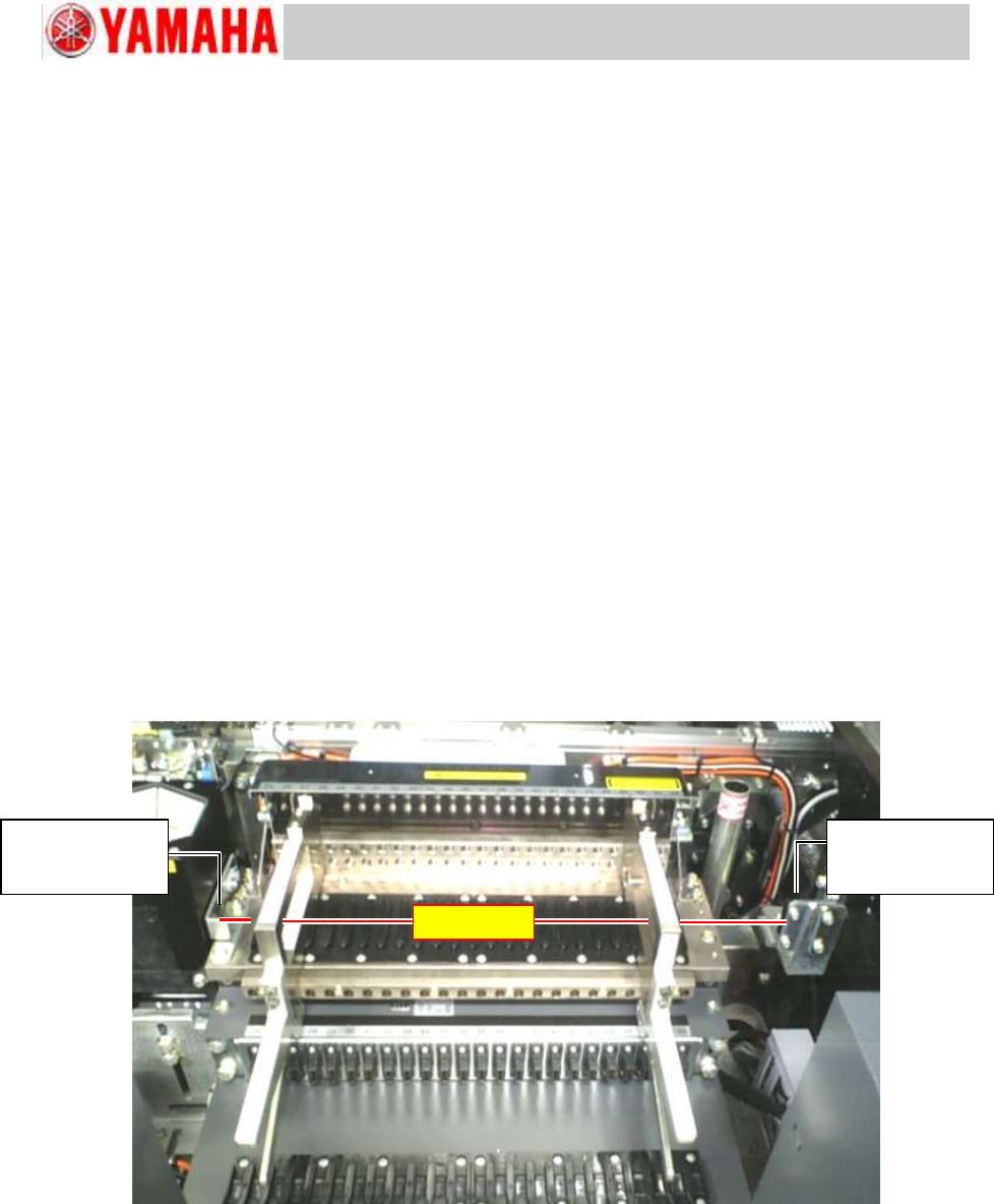
Step 1 Set the Pickup position adjustment jig on the both ends of the feeder bank.
When it is difficult to find the optical axis, you can move the tool a little inward from the end.
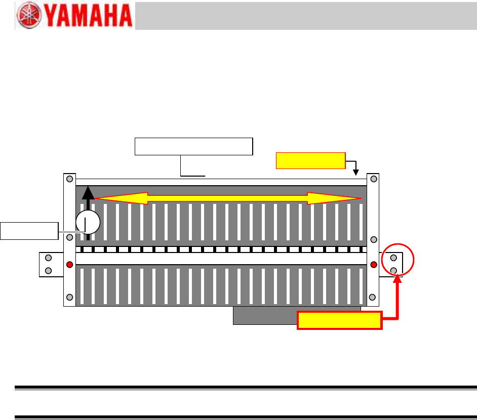
Step 2 Adjust the positions of the emitter and the receiver of the feeder floating detection
sensor.
Adjust the sensor position so that the optical axis of the sensor put through the holes of the
Pickup position adjustment jigs.
Figure 76
Step 3 Set a SS feeder to a feeder set position to make sure that the optical axis of the sensor
is not blocked by the feeder.
If it is not blocked, the sensor positions are adjusted properly.
Step 4 Remove the Pickup position adjustment jigs from the feeder bank and make sure that
no tools or parts are left inside the machine.
Feeder floating
detection sensor
Receiver
Optical axis
Feeder floating
detection sensor
Emitter

Service Engineer
Service Information
SI0907002E-003=YS machine’s tape cutter cleaning and lubrication
63/63
7. Update history
Revision No.
Updated content
Reference
Issued date
-001
First release
December 13, 2011
-002
The description on the brush as a tool to apply grease for
lubrication has been added.
March 22, 2016
The description on the adjustment of the blade-to-blade
clearance by the shim has been added.
The procedure for the optical axis direction of the feeder
floating detection sensor has been added.
The Test paper for tape cutter performance has been
introduced.
The procedure to apply turbine oil to the cutter blade has
been added.
-003
The test paper for the tape cutter performance has
been changed to the test emboss tape for the tape
cutter performance (TEST TAPE, CUTTER /
KLW-M8825-00 Thickness: 0.18mm).
P.9
P.47
February 21, 2017