雅马哈YSM切刀更换和保养方法..pdf - 第61页
Service Engineer Service Information SI0907002E - 003 = YS machine’s tape cu tter cleaning and lubrication 61 / 63 5) Move the dial gauge f rom side to side again to m ake sure that there is no misalignm ent , and then f…
Service Engineer
Service Information
SI0907002E-003=YS machine’s tape cutter cleaning and lubrication
60/63
5 When the feeder bank position needs to be adjusted mechanically
This section describes how to mechanically adjust the feeder bank position when the positioning
plate for the feeder bank is not positioned properly.
5.1 Required items
YAMAHA standard tools
Other tools
Item
Part name
Part number
Qty
Versatile magnet stand bracket
PLATE BASE MAGNET
KJJ-M22JF-10
1
YS24-/YS12-specific magnet stand bracket
MAGNET BASE JIG
KHY-M8808-A0
1
Dial gauge mini-stand (NOGA NF1300)
1
Table 7
5.2 Adjust the feeder bank position mechanically
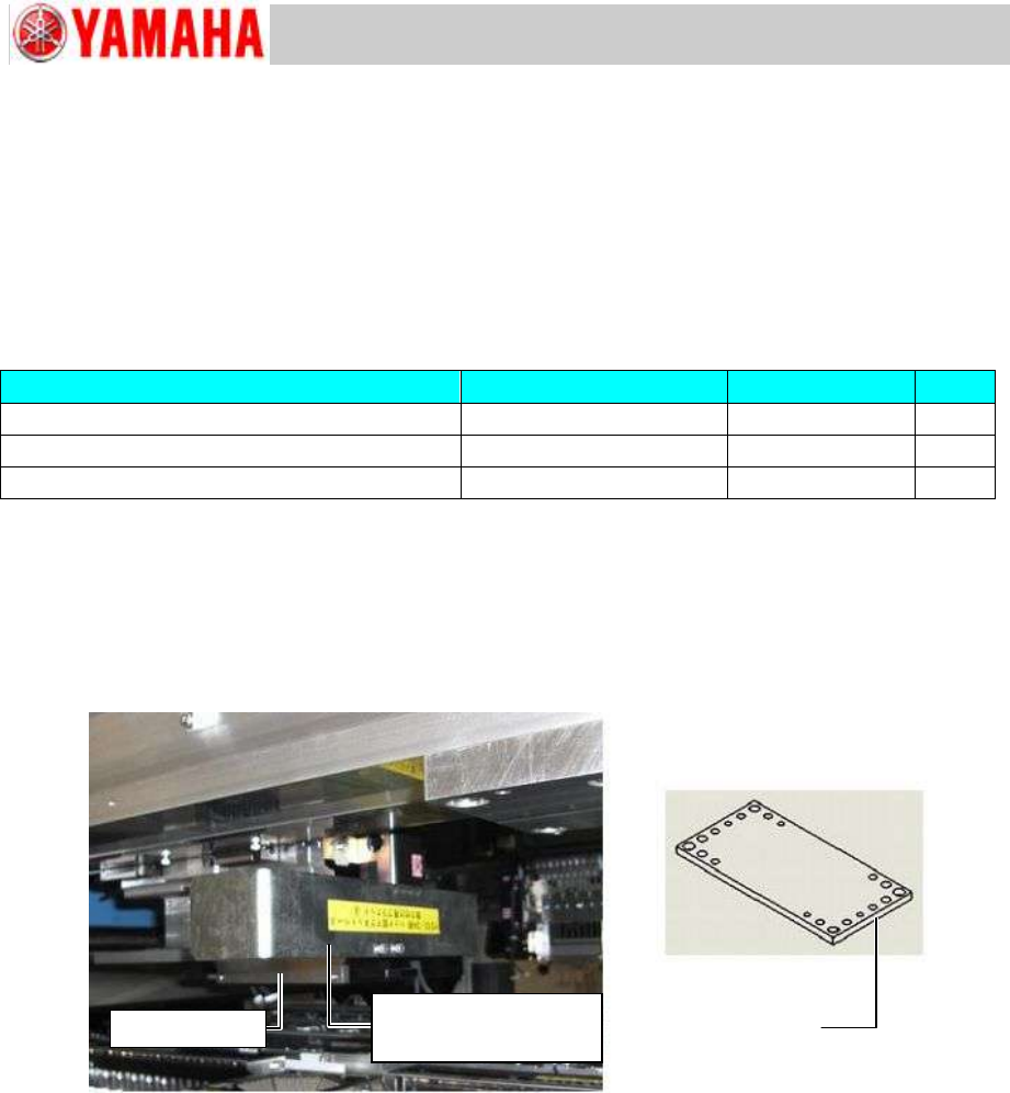
Step 1 Attach the magnet stand bracket to the machine head.
For the machines equipped with a scan camera, use a magnet stand bracket for YS24 &
YS12. For the machines without a scan camera, use a versatile magnet stand bracket.
Figure 74
Step 2 Attach the dial gauge mini-stand (NF1300) to the magnet stand bracket, and set the dial
gauge to it.
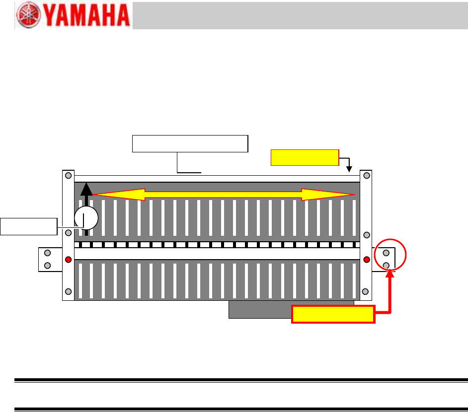
Step 3 Zero the dial gauge on the reference side of the feeder bank.
Note:
The reference side of the feeder bank is on the right side end (viewed from the front side of the
machine).
Step 4 Correct the misalignment of the feeder bank.
1) Loosen the screws fastening the target feeder bank.
2) Loosen the screws fastening the feeder bank positioning block which is NOT on the
reference side.
3) Move the dial gauge from side to side to measure and adjust the feeder bank position
so that it is parallel to the X-axis.
4) Tighten the loosened screws.
Versatile magnet
stand bracket
Magnet stand bracket
for YS24 & YS12
Scan camera
Service Engineer
Service Information
SI0907002E-003=YS machine’s tape cutter cleaning and lubrication
61/63
5) Move the dial gauge from side to side again to make sure that there is no misalignment,
and then fully tighten all the loosened screws.
<Specified value>
Parallelism to the X-axis: 0.02 mm or below (0.04 mm around the center of the feeder
bank)
Figure 75
Step 5 Remove the measuring tools from the machine head.
Caution:
Be sure to remove all the measuring tools.
Step 6 Attach the Pickup position adjustment tool on the machine and adjust the feeder
pickup positions.
See “4 Check and adjust the pickup positions of the feeders” for the details.
Reference side
Dial gauge
DO NOT loosen.
Feeder positioning plate
Service Engineer
Service Information
SI0907002E-003=YS machine’s tape cutter cleaning and lubrication
62/63
6 Adjust the optical axis direction of the feeder floating detection sensor
After the feeder bank is dismounted and reinstalled, the optical axis of the feeder floating detection
sensor may have been misaligned. Make sure to check the optical axis direction and if it is
misaligned, adjust it.
6.1 Required item
YAMAHA standard tools
Pickup position adjustment jigs
(It is recommended to prepare 2 sets. If you can prepare only 1 set, use a feeder as a
substitute.)
6.2 Check and adjust the optical axis direction
Adjust the optical axis direction by adjusting the position of the feeder floating detection sensor.
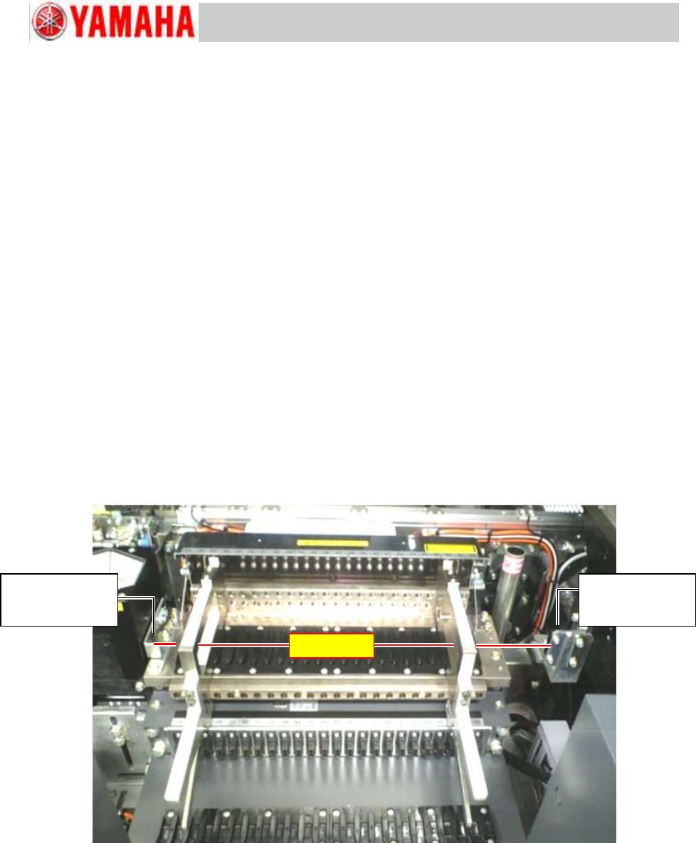
Step 1 Set the Pickup position adjustment jig on the both ends of the feeder bank.
When it is difficult to find the optical axis, you can move the tool a little inward from the end.
Step 2 Adjust the positions of the emitter and the receiver of the feeder floating detection
sensor.
Adjust the sensor position so that the optical axis of the sensor put through the holes of the
Pickup position adjustment jigs.
Figure 76
Step 3 Set a SS feeder to a feeder set position to make sure that the optical axis of the sensor
is not blocked by the feeder.
If it is not blocked, the sensor positions are adjusted properly.
Step 4 Remove the Pickup position adjustment jigs from the feeder bank and make sure that
no tools or parts are left inside the machine.
Feeder floating
detection sensor
Receiver
Optical axis
Feeder floating
detection sensor
Emitter