雅马哈YSM切刀更换和保养方法..pdf - 第21页
Service Engineer Service Information SI0907002E - 003 = YS machine’s tape cu tter cleaning and lubrication 21 / 63 2) Remove the fan and its mounting plate at the r ight side base of the controller. Disconnect the power …
Service Engineer
Service Information
SI0907002E-003=YS machine’s tape cutter cleaning and lubrication
20/63
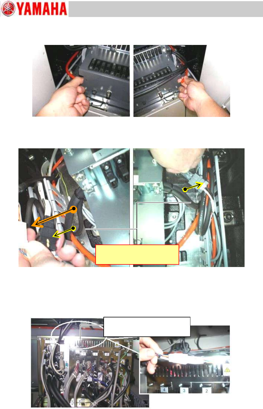
Step 4 Disconnect air hoses of the feeder bank at each quick joint.
Figure 21
Step 5 Disconnect the harnesses of the feeder bank(s) led to the right and left cable ducts at
each connector. Draw out the disconnected harnesses to the feeder bank side.
Figure 22
Step 6 Disconnect the harnesses of the feeder bank(s) at each connector.
1) The harness of each feeder bank (right side and the left side) led into the machine base
are connected in the duct at the rear upper part of the controller. Disconnect the
harnesses.
Figure 23
Connected in the duct at the rear
upper part of the controller
Inside the duct at the upper part on
the back side of the controller
Service Engineer
Service Information
SI0907002E-003=YS machine’s tape cutter cleaning and lubrication
21/63
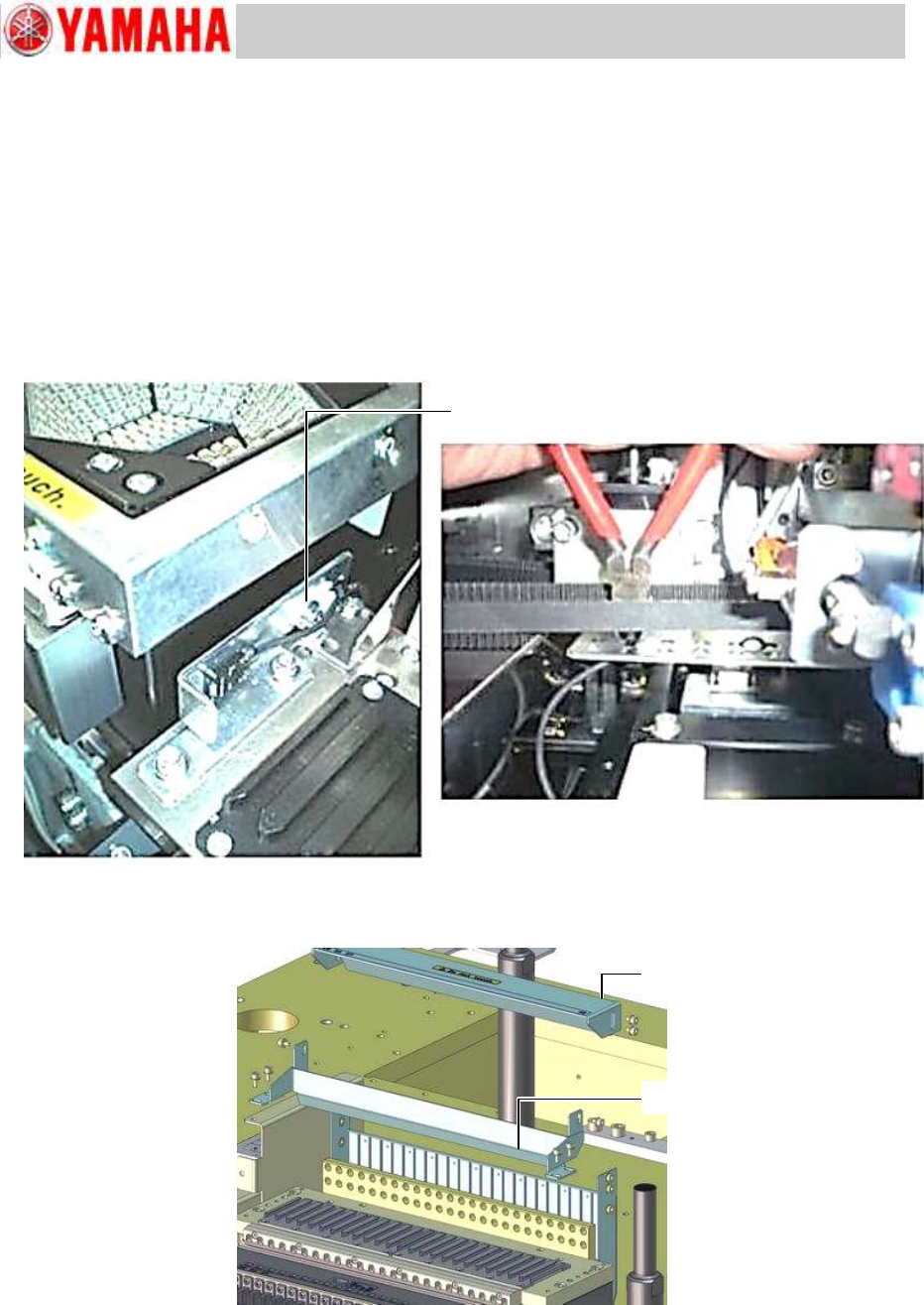
2) Remove the fan and its mounting plate at the right side base of the controller. Disconnect
the power connector of the fan and draw it out from the cable duct.
Step 7 Remove the feeder floating detection sensor on the feeder bank.
Remove the feeder floating detection sensor (Receiver side) on the feeder bank together with
the bracket.
The sensor harness is secured to the back side of the feeder bank with cable ties. Cut the
cable ties and free the harness.
Make sure that the sensor harness is NOT attached to the back side of the feeder bank
before removing the feeder bank from the machine.
Figure 24
Step 8 Remove the upper cover of the tape guide slope. Then remove the slope bracket.
Figure 25
Note:
The fixing screws have a washer on them. Be careful not to lose the washers.
Upper cover
Slope bracket
Fixing screw of the cable clamp.
Service Engineer
Service Information
SI0907002E-003=YS machine’s tape cutter cleaning and lubrication
22/63
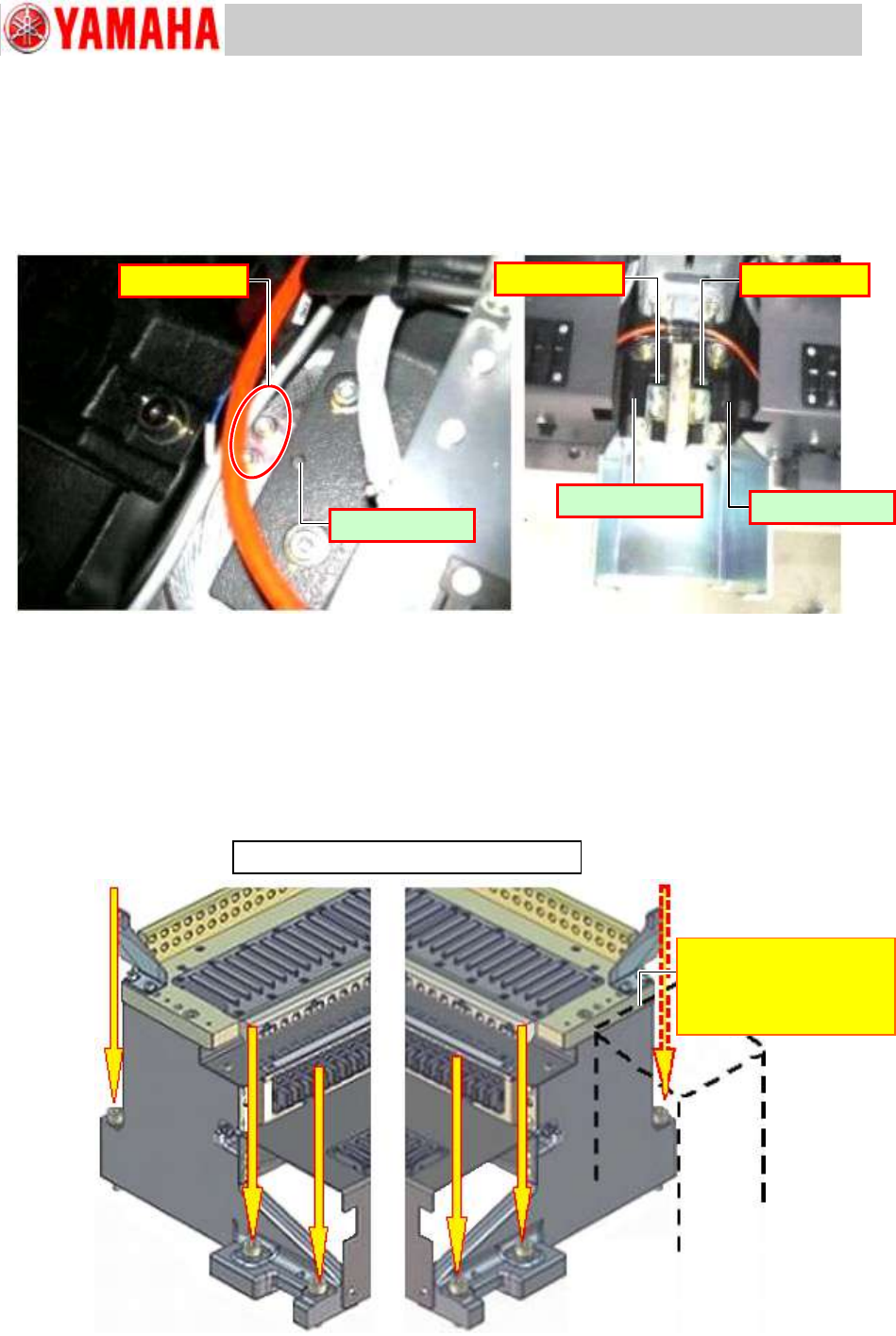
Step 9 Check that the feeder bank positioning plates (where positioning pins are located) are
secured properly. If loose, secure them properly.
Note:
If the feeder bank positioning plates are loose, when you reassemble the removed feeder
bank later on, you cannot position it properly.
Figure 26
Step 10 Remove the screws fastening the feeder bank(s) on the machine (six screws per feeder
bank - three screws each on the both sides).
Note:
The feeder bank fixing screws are tightened with high torque. When you loosen the screws
with a wrench, make sure that no interfering objects exist in the work area.
When loosening the screws close to the Multi camera, be careful not to interfere with the
camera.
Figure 27
Fixed feeder bank with 24 feeder positions
[Multi camera]
The workability is poor
because of the cover of
the light.
No looseness
Positioning pin
Positioning pin
Positioning pin
No looseness
No looseness