雅马哈YSM切刀更换和保养方法..pdf - 第19页
Service Engineer Service Information SI0907002E - 003 = YS machine’s tape cu tter cleaning and lubrication 19 / 63 3.4. 2 Rem ove the Fix ed feeder bank with 24 feeder positi on s Note: For YS100 and YS88 machines equ ip…
Service Engineer
Service Information
SI0907002E-003=YS machine’s tape cutter cleaning and lubrication
18/63
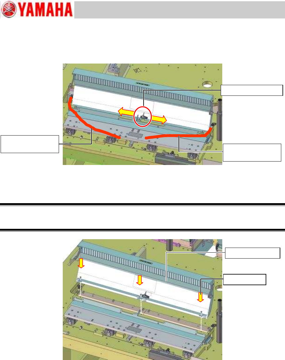
Step 9 Disconnect the air hoses used for driving the tape cutter at each quick joint.
Disconnect the air hoses from the bulkhead quick joint at the center of the tape cutter.
Figure 16
Step 10 Remove the tape guide slope Assy. from the machine by removing its three (3) fixing
screws.
Warning:
When the tape guide slope is removed, the cutter blade inside will be exposed. Please be extremely
careful when working on the tape cutter to avoid getting injured.
Figure 17
Bulkhead quick joint
Air hose for driving
the tape cutter
Air hose for driving
the tape cutter
Tape guide slope
Fixing screw
Service Engineer
Service Information
SI0907002E-003=YS machine’s tape cutter cleaning and lubrication
19/63
3.4.2 Remove the Fixed feeder bank with 24 feeder positions
Note:
For YS100 and YS88 machines equipped with an sATS, disconnect the sATS from the
machine first for the better workability.
For further information, see Service Information “SI0911001E = How to install the sATS/dYTF
for YS100, YS88, YG100R and YG88R machines”.
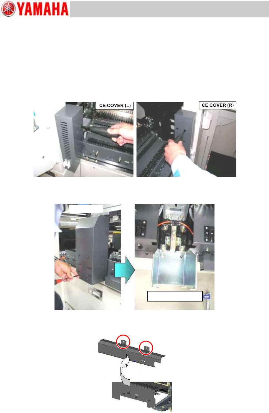
Step 1 Remove the CE covers on the right and left side of the feeder bank.
Figure 18
Step 2 Remove the center cover and its mount bracket at the center of the feeder bank.
Figure 19
Step 3 Remove the cover of the tape cutter driving valve.
Figure 20
Center cover
Center cover bracket
Service Engineer
Service Information
SI0907002E-003=YS machine’s tape cutter cleaning and lubrication
20/63
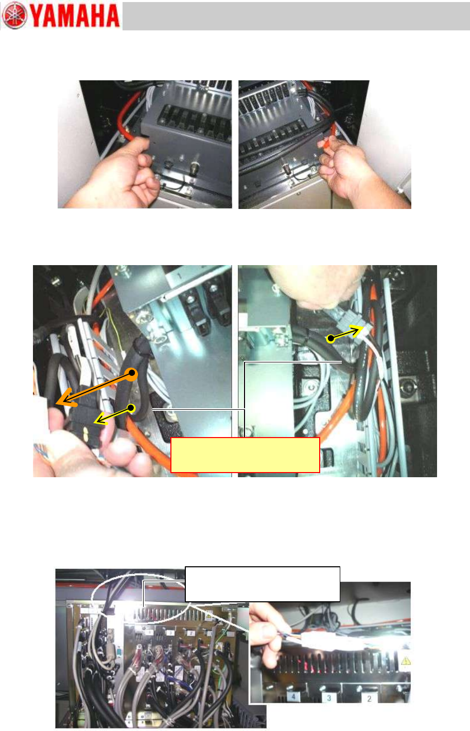
Step 4 Disconnect air hoses of the feeder bank at each quick joint.
Figure 21
Step 5 Disconnect the harnesses of the feeder bank(s) led to the right and left cable ducts at
each connector. Draw out the disconnected harnesses to the feeder bank side.
Figure 22
Step 6 Disconnect the harnesses of the feeder bank(s) at each connector.
1) The harness of each feeder bank (right side and the left side) led into the machine base
are connected in the duct at the rear upper part of the controller. Disconnect the
harnesses.
Figure 23
Connected in the duct at the rear
upper part of the controller
Inside the duct at the upper part on
the back side of the controller