雅马哈YSM切刀更换和保养方法..pdf - 第58页
Service Engineer Service Information SI0907002E - 003 = YS machine’s tape cu tter cleaning and lubrication 58 / 63 3. 7 Check the tape cutter o perati on Step 1 Ch eck the condition of th e reassembled parts and fully ti…

Service Engineer
Service Information
SI0907002E-003=YS machine’s tape cutter cleaning and lubrication
57/63
Move the sATSII back to its original position.
Service Engineer
Service Information
SI0907002E-003=YS machine’s tape cutter cleaning and lubrication
58/63
3.7 Check the tape cutter operation
Step 1 Check the condition of the reassembled parts and fully tighten their screws.
Step 2 Attach the removed CE safety covers.
Make sure to attach the CE safety covers on the both sides of the feeder bank.
Caution:
Do not start the machine without installing the CE safety covers to the machine. The machine operator
and/or bystanders may get injured. Also emergency stop status cannot be cancelled depending on the
machine.
Step 3 Make sure that no tools or parts are left inside the machine.
Step 4 Unlock the padlock on the air supply/shut-off switch. Turn ON the air supply to the
machine.
Make sure that no air leakage is observed and air is supplied to the feeder banks and their
tape cutter properly.
Step 5 Power ON and start the machine.
Step 6 Check the tape cutter operation manually by selecting the [Unit] button
[Feeder] tab
[Cutter] button.
Step 7 Check the tape cutter performance.
Use the test emboss tape for tape cutter performance (Thickness: 0.18mm) for the check.
Important:
Make sure to use the test emboss tape for tape cutter performance (TEST TAPE, CUTTER / KLW-M8825-00).
If you cannot prepare the test tape, use a 0.18mm thick emboss tape as a substitute.
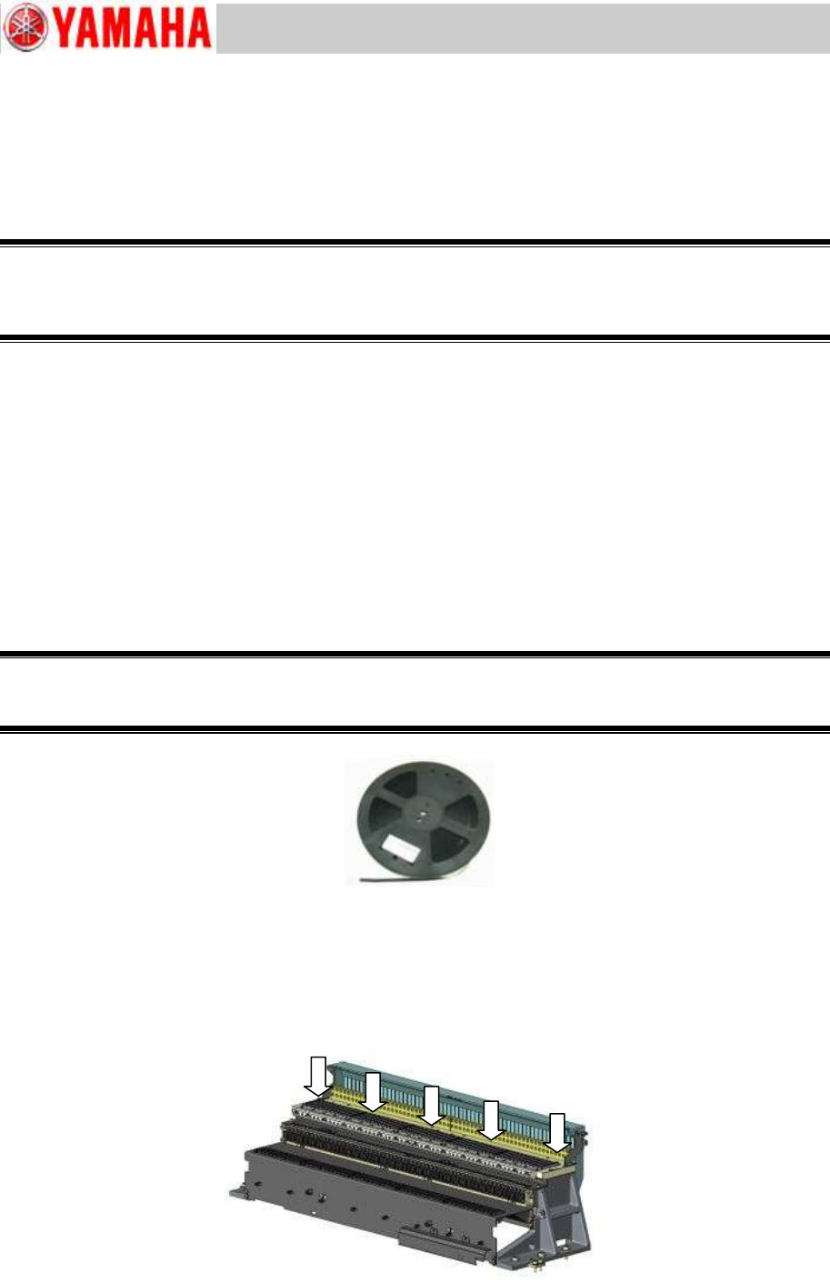
Figure 71
[Where to check the cutter blade sharpness]
Insert the test tape (0.18mm thick) from the upper part of the slope and make sure that it is cut
properly.
Regardless of the cutter size, check the cutter performance at the five (5) positions shown in the
figure below.
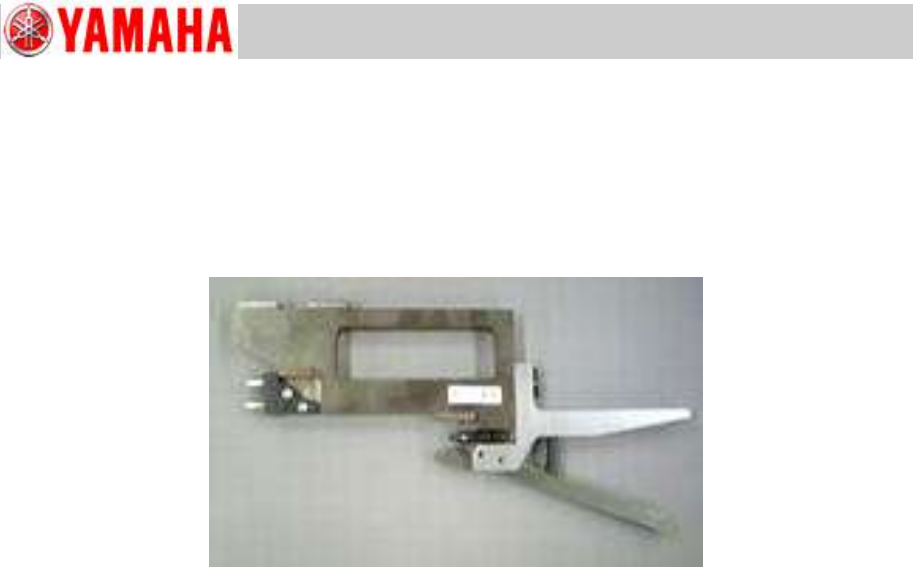
Figure 72
TEST TAPE, CUTTER
KLW-M8825-00
Service Engineer
Service Information
SI0907002E-003=YS machine’s tape cutter cleaning and lubrication
59/63
4 Check and adjust the pickup positions of the feeders
Step 1 Click the [Utilities] button to start up the CalibSm adjustment utility.
Click the [005 FeederPos] button on the CalibSm main menu.
Step 2 Set the SS feeder pickup position adjustment jig on the machine.
Figure 73
Step 3 Enter the offset values of the jig. Then measure the coordinates of the reference
feeders of all the dismounted feeder banks.
* If the feeder coordinates are out of acceptable range, use the [XYExecute] button to perform
the adjustment.
Step 4 When the measurement and adjustment of all the reference feeder coordinates are
completed, click the [Plate check] button to check all the feeder coordinate data.
Should there be abnormal values (indicated in red), teach the coordinates again and perform
the adjustment.
Note:
See Service Information “SI0907004E YS24, YS24X_Installation and adjustment procedures”
for the detailed operation procedures.
Note:
If feeder coordinate data indicated in red are way out of specified range and/or because of this
simultaneous pickup is not possible, see “5 When the feeder bank position needs to be
adjusted mechanically”.