MIL- STD-883F 2004 TEST METHOD STANDARD MICROCIRCUITS.pdf - 第298页
MIL-STD-883F METHOD 2017.8 18 June 2004 8 Class H Class K f. Conduc tive att achment medi a which c omes cl oser t han 1.0 mil to any funct ional met allizat ion or el ement whic h is not elec tric ally c ommon. g. Crack…
MIL-STD-883F
METHOD 2017.8
18 June 2004
7
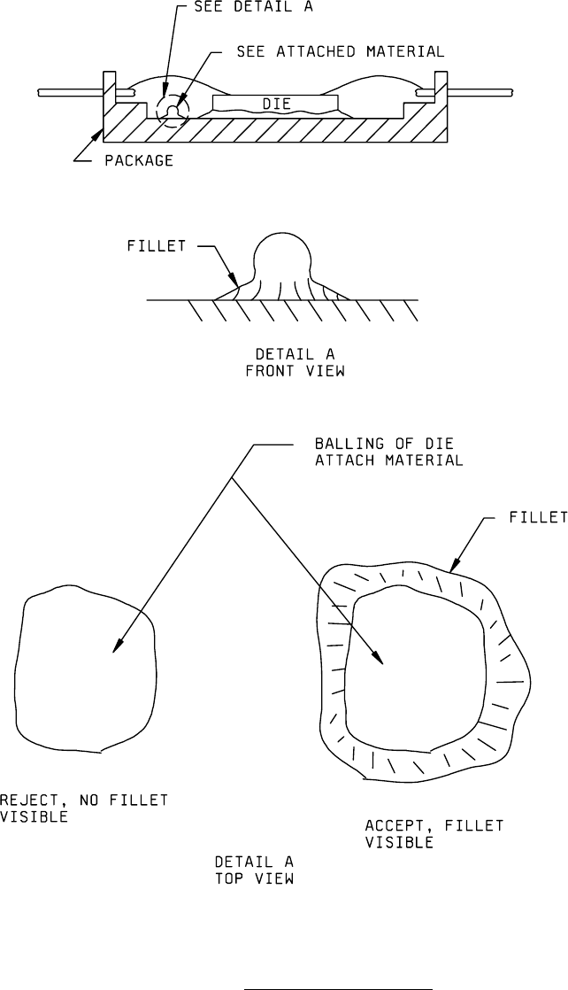
FIGURE 2017-3. Balling of die attach material
.
MIL-STD-883F
METHOD 2017.8
18 June 2004
8
Class H Class K
f. Conductive attachment media which comes closer than 1.0 mil to any functional metallization or element which is
not electrically common.
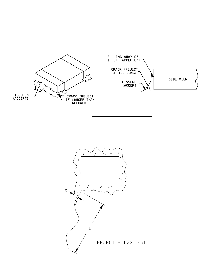
g. Cracks in the surface of the attachment media greater than 5.0 mils in length or 10 percent of the contact
periphery, whichever is greater.
NOTE: Irregularities such as fissures or pullback at the edges of the adhesive are not considered cracks. (see Figure
2017-3a)
FIGURE 2017-3a. Adhesive irregularities and cracks
.
h. Adhesive strings where the diameter of the string at the point of attachment is less than 50 percent of the
maximum length of the string. (see Figure 2017-3b)
FIGURE 2017-3b. Adhesive String Criteria
.
MIL-STD-883F
METHOD 2017.8
18 June 2004
9
Class H Class K
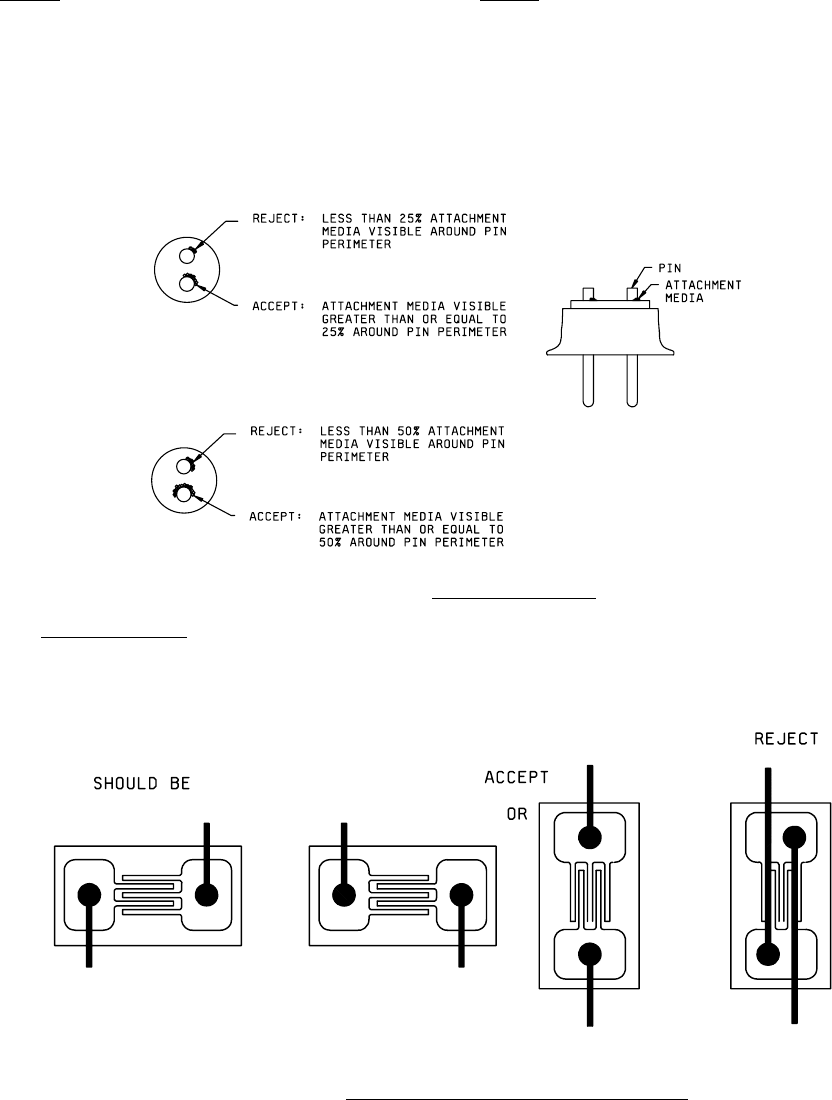
i. For element connection to a package post lead, attachment media visible for less than 25 percent of the post
perimeter. When the post also serves for substrate attachment, media shall be visible for no less than 50 percent
of the post perimeter. (see Figure 2017-3C)
j. Cold solder joints.
k. For thin film NiCr only, nonconductive adhesive material that covers more than 10 percent of the active area of
deposited resistor material.
FIGURE 2017-3c. Package Post Criteria
.
3.1.3 Element orientation
. Element not located or oriented in accordance with the applicable assembly drawing of the
device. Elements whose bond and electrical configuration is symmetrical may be rotated unless otherwise stated in the
assembly drawings.
FIGURE 2017-3d. Acceptable Symmetrical Element Orientation.