MIL- STD-883F 2004 TEST METHOD STANDARD MICROCIRCUITS.pdf - 第578页
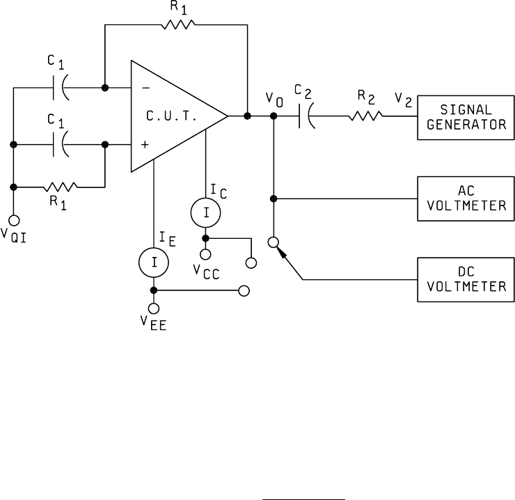
MIL-STD-883F METHOD 4007 1 May 1968 2 FIGURE 4007-1. AGC t est c irc uit .
MIL-STD-883F
METHOD 4007
1 May 1968
1
METHOD 4007
AUTOMATIC GAIN CONTROL RANGE
1. PURPOSE
. This method establishes the means for measuring the automatic gain control range of a linear amplifier.
1.1 Definitions
. The following definition shall apply for the purpose of this test method.
1.1.1 Automatic gain control range (AGC)
. The AGC range is the total change in voltage gain which may be achieved by
application of a specified range of dc voltages to the AGC input terminal of the device.
AGC = 20
A
A
v
v
log
max
min
2. APPARATUS
. The apparatus shall consist of a sweep generator, voltage source, resistors, capacitors, an ac
voltmeter, and a distortion analyzer.
2.1 Sweep generator
. The sweep generator must cover the frequency range of the amplifier under test. It shall have an
adjustable output level which is flat over the sweep range. It shall be capable of single frequency operation.
2.2 Voltage source
. The voltage source shall be capable of supplying the specified AGC voltages to the test circuit. The
voltage source shall be free of noise or ripple at its outputs.
2.3 Capacitors and resistors
. The capacitors and resistors shall be within 1 per cent or better of the specified values and
stable over the test temperature range.
2.4 AC voltmeter
. The ac voltmeter shall be capable of measuring the amplifier output voltage without loading and shall
have a frequency range that will cover the amplifier under test.
2.5 Distortion analyzer
. The distortion analyzer or meter shall be usable over the passband of the amplifier and shall not
load the amplifier.
3. PROCEDURE
. The test circuit shown on figure 4007-1 shall be used for this test. R
L
and C
1
shall be selected to
properly load and decouple the circuit, respectively. The AGC voltage is set for maximum gain. The input signal is applied
(constant frequency) and increased until the output exhibits maximum allowable distortion. The generator is swept over the
prescribed range and the bandwidth noted.
The AGC voltage is varied over the specified range and the reduction in gain is measured. The above measurements are
repeated and the bandwidth and signal handling capability recorded.
4. SUMMARY
. The following details shall be specified in the applicable acquisition document for specified values of C
1
and R
L
.
a. AGC range.
b. Test frequency range.
c. Increase in bandwidth over the AGC range.
d. Maximum reduction in output impedance, where applicable.
e. Minimum reduction in input signal capability, where applicable.
f. Any other variations when applicable, such as power variation, overloading, limitations as to linearity of gain
response versus AGC voltage, etc.
g. Test temperature(s). Unless otherwise specified, all parameters shall be measured at the minimum and maximum
specified ambient operating temperature and at 25°C ambient.
MIL-STD-883F
METHOD 4007
1 May 1968
2
FIGURE 4007-1. AGC test circuit
.

MIL-STD-883F
METHOD 5001
20 November 1969
1
METHOD 5001
PARAMETER MEAN VALUE CONTROL
1. PURPOSE
. The purpose of this method is to define a technique for assuring a conformance to a maximum or
minimum mean of a parameter measured in any test method listed in section 3000 and 4000 of this standard. This method
is not intended for general application to acquisitions where it is important only to assure that device parameters are
between specified limits. It is intended for use only where it is necessary to control the average or mean value for a given
parameter throughout a lot of shipment of devices. When this method is employed, it is expected that the specified group of
devices tested will be packaged for shipment as a group together with the required data. It is also expected that some
provisions will be required for special marking of devices subjected to this method to identify that they have met the selection
criteria involved and that they are therefore not directly interchangeable with identical devices which have not been
controlled or selected in this manner.
2. APPARATUS
. For distribution control, it is desirable for the measuring equipment to have data logging capability in
addition to the capabilities listed in section 3000 and 4000. The data shall be recorded and analyzed to compute the
average value of a group of microelectronic devices. The size of the group shall be specified in the applicable acquisition
document.
3. PROCEDURE
. Microelectronic devices shall be separated into groups. Each group will be tested in accordance with
the specified test method. The reading from each device will be recorded. When all devices in the group have been tested,
the recorded data shall be averaged (or the mean value computed) and compared against a maximum or minimum limit
specified in the applicable acquisition document.
4. SUMMARY
. The following details must be specified in the applicable acquisition document:
a. Absolute maximum and minimum limits.
b. Maximum or minimum limits on the average or mean.
c. Group size.
d. Requirements for data logging, special marking, and special provisions for group packaging and shipment, where
applicable.