MIL- STD-883F 2004 TEST METHOD STANDARD MICROCIRCUITS.pdf - 第378页
MIL-STD-883F METHOD 2023.5 19 August 1994 6 3.2.2 Lot accept ance proc edure . Eac h ass embly lot s hall r eceive a pos t-s eal bond wir e integr ity ac ceptanc e test . A separat e assembl y lot ac ceptanc e tes t is r…
MIL-STD-883F
METHOD 2023.5
19 August 1994
5
3.2.1.7 Process capability study. After the wirebond process has been demonstrated to be in a condition of stability and
statistical control, a process capability study shall demonstrate that the probability of any device failing the minimum
post-seal bond strength is P <.0001. The probability must meet the accumulative probability at the device level and not at
the individual wire level. The distributional form of the post-seal bond strengths shall be statistically evaluated for
conformance to the selected sampling distribution (e.g., Gaussian, lognormal, Wiebull, etc.). The capability study sample
size shall be sufficient to detect a shift in the distribution of the worst case package/die combination to a 100 parts per
million level. The beta risk to the consumer shall be .001 or less. (See Appendix A for normal distribution example.) The
process capability study shall be performed periodically. The capability study may be accomplished by characterizing the
wire pull strengths of one or more worst case package/die combinations. Selection of the worst case package/die
combinations should consider wire geometry, number of wires, pads and post sizes, etc. The characterization results from
worst case package/die combinations must be readily extended to all devices.
3.2.1.8 Control limits and action procedures
. The results of the evaluations in 3.2.1.6 and 3.2.1.7 shall be used in
determining control limits and action procedures for the wire bond operation. A destructive wire bond strength sampling plan
for each wire bonder shall include start and completion of each assembly lot, frequency of sampling the assembly lot, and
changes in operators (manual wire bonding only), wire spools, package lots, or setup conditions. The bond strength data
shall include the force required for failure, the physical location of failure, and the nature of the failure. Electrical rejects from
the same wafer lot may be used for the destructive wire bond pulls. In the event that bond wire strengths are outside the
predicted values for the wire, or class of wires with similar geometry, the bonder shall be inactivated immediately and not
returned to production until tests show that the operation is back under statistical control. A procedure for the traceability,
recovery, and disposition of all units bonded since the last successful bond strength test is required.
3.2.1.9 Time and temperature characterization
. Initially, a time and temperature characterization shall be performed for
each major type of wire bond metallurgical interface (e.g., gold/aluminum, etc.) to determine the electrical and mechanical
integrity of the wire bonds with respect to such factors as; flexing of wire bonds due to thermal expansion, and microcracks
or microvoids at the metallurgical interface. Evidence from the characterization shall demonstrate that the integrity of the
bonds is sufficient for a device to function over its expected life. Life usage conditions shall exceed 50,000 cycles from a 0 -
85 degree Celsius temperature range at the bonds. Time and temperature degradation factors for accelerated testing must
be justified against these minimal life usage conditions.
3.2.1.10 Wire bond integrity
. If pre-burn-in, interim and post burn-in electrical failures (opens/shorts), qualification, or
quality conformance inspection failures indicate questionable wire bond integrity then an analysis is required to verify the
bond integrity. If any bond is confirmed to be defective; the applicable inspection lot or sublot will be rejected, an evaluation
performed to determine the cause of the bond failure, corrective actions implemented based on the evaluation, and
disposition of other affected inspection lots or sublots. The failure analysis and corrective actions will be retained and made
available to the qualifying activity upon request.

MIL-STD-883F
METHOD 2023.5
19 August 1994
6
3.2.2 Lot acceptance procedure. Each assembly lot shall receive a post-seal bond wire integrity acceptance test. A
separate assembly lot acceptance test is required for each wire bonder, and for any changes in setup conditions, wire spool,
package lot, or wafer lot, unless such differences have been demonstrated to be statistically insignificant. A post-seal
destructive wire bond sampling and test plan with the following minimum requirements shall be documented.
a. More than one device shall be subjected to the acceptance test. Electrical, non-wire bond related visual, or
package seal rejects may be used for the post-seal wire bond test.
b. The destructive wire pulls shall be evaluated in meeting the post-seal bond strength limits in MIL-STD-883, Method
2011, or as established in 3.2.1.7. The assembly lot shall be accepted if the wire bond strengths meet the
requirements of sections c, d, and e below.
c. All wires or a minimum of 50 randomly selected wires shall be pulled from each sampled device. The post-seal
bond strength distribution(s) must demonstrate that the wire bond process is in statistical control, has not changed
with respect to the distribution characterized for a one-sided lower control limit, and no single destructive pull is
less than the specified post-seal bond strength limit. The sample size shall be sufficient to demonstrate that the
statistical distribution of all wires pulled has not changed with respect to central tendency or dispersion in such a
way as to violate a p < .0001 at the device level. The beta risk to the consumer shall be .01 or less. The method of
statistical analysis shall be documented and approved by the qualifying activity.
d. A minimum of 8 wires shall be evaluated from each sampled device to represent the worst case wires as
determined to potentially violate the lower specification limit. Their wire pull strengths shall be within the predicted
tolerances established in 3.2.1.6. Any wire pull strengths outside the predicted tolerance in the characterized
distribution shall require evaluation as to the cause of the out of control condition, and additional worst case wires
shall be pulled to determine whether the wire bond strength distribution meets a probability at the wire level of
P < 1-[.9999**(1/n)] (n = number of bonding wires in the package). The lot is rejected if this criteria is not met.
e. If any bond fails the acceptance criteria, a documented action plan shall be followed to determine the cause of the
failure. Wire bond failures verified as non-bond related shall be documented, and additional post-seal wire bond
pulls shall be conducted to demonstrate statistical control as described in 3.2.2.1.c and d. If a failure is verified as
bond integrity related (e.g., contamination on wire, glassivation on the bonding pad, etc.), all devices within the
applicable assembly lot shall be rejected. Wire bonding shall be suspended on the applicable bonding equipment
until a failure analysis, MIL-STD-883, method 5003, of the failed bond is performed and corrective action is
implemented and recorded.
4. SUMMARY
. The following details shall be specified in the applicable acquisition document:
a. The applied lifting force if other than as specified in 3.1.
b. The sampling, acceptance, or screening requirements.
c. The percent defective allowable (PDA) as applied to the number of failures with respect to the number of wires
tested.
d. The requirements for reporting of failure categories, when applicable.
MIL-STD-883F
METHOD 2023.5
19 August 1994
7
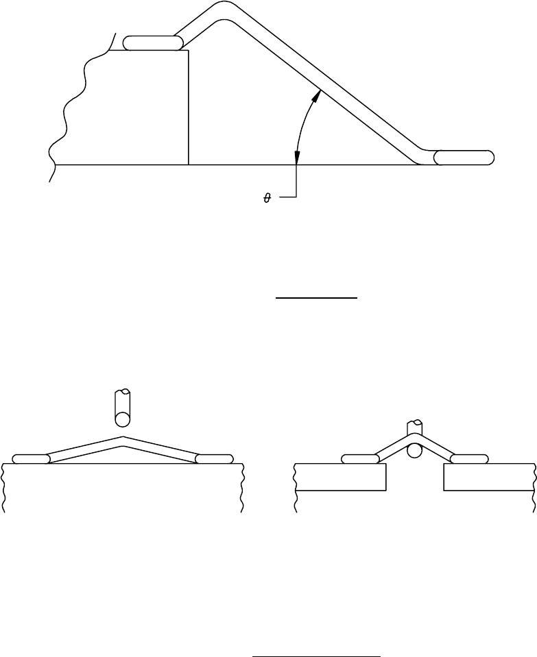
FIGURE 2023-1. Wire loop angle
.
FIGURE 2023-2. Flat loop wire pull testing
.