MIL- STD-883F 2004 TEST METHOD STANDARD MICROCIRCUITS.pdf - 第429页
MIL-STD-883F METHOD 2032.2 18 June 2004 23 Class H Class K 3.1. 6 c . Any s harp (c learl y defined) color change 3.1.6 c. Same as class H. within 0. 1 mil of t he termi nal. NOTE: A shar p color change cl ose to t he te…
MIL-STD-883F
METHOD 2032.2
18 June 2004
22
Class H Class K
3.1.6 Thin film resistor defects, "high magnification"
.
No element shall be acceptable that exhibits:
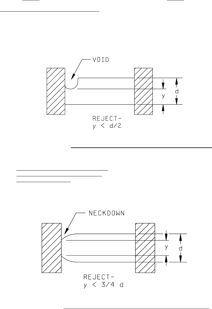
a. Voids at the terminal that reduces the a. Same as Class H
resistor width to less than 50 percent of
the original resistor width (see figure
2032-13h).
FIGURE 2032-13h. Class H film resistor width reduction at terminal by voids criterion
.
b. Neckdown at the terminal that reduces the
b. Same as Class H.
resistor width to less than 75 percent of
the original resistor width
(see figure
2032-14h).
FIGURE 2032-14h. Class H film resistor width reduction at terminal by necking criterion
.
MIL-STD-883F
METHOD 2032.2
18 June 2004
23
Class H Class K
3.1.6 c. Any sharp (clearly defined) color change 3.1.6 c. Same as class H.
within 0.1 mil of the terminal.
NOTE: A sharp color change close to the
terminal usually indicates an abrupt
reduction of resistor film thickness.
This color change usually occurs in a
straight line parallel to the terminal.
A gradual color change, or a nonuniform
or mottled color anywhere in the resistor,
is not cause for rejection.
d. Any resistor film lifting, peeling or d. Same as class H.
blistering.
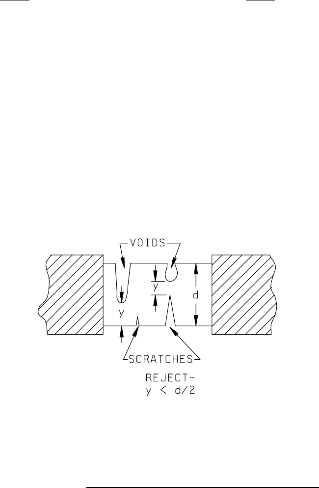
e. Reduction of resistor width, resulting from e. Same as class H.
voids, scratches, or a laser trim kerf or a
combination of these, that leaves less than
50 percent of the narrowest resistor width
(see figure 2032-15h).
PRECAUTIONARY NOTE: The maximum allowable
current density requirement shall not be exceeded.
FIGURE 2032-15h. Class H resistor width reduction by voids and scratches criteria
.
MIL-STD-883F
METHOD 2032.2
18 June 2004
24
Class H Class K
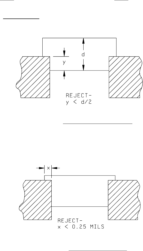
3.1.6 f. Contact overlap between the metallization and 3.1.6 f. Same as Class H.
the resistor in which the width dimension "y"
is less than 50 percent
of the original resistor
width (see figure 2032-16h).
FIGURE 2032-16h. Class H metal/resistor overlap criterion
.
g. Contact overlap between the metallization g. Same as class H.
and the resistor in which the length
dimension "x" is less than 0.25 mil
(see figure 2032-17h).
FIGURE 2032-17h. Class H contact overlap criterion
.