XP-142E Operator's Guide-TUT-XP142-1.1E.pdf.pdf - 第13页
Machine Front (Side 1) Machine Rear (Side 2) 13 14 15 12 10 11 4 16 XP1ON202a 9 8 7 6 3 4 5 2 1 XP1ON201a 9 1.1 Component Names and Functions Chapter 1: Machine Configuration TUT -XP142-1.1E 1-2 XP-142E Operator ’s Guide

Chapter 1
Machine Configuration
1.1 Component Names and Functions
TUT-XP142-1.1E
1-1XP-142E Operator’s Guide
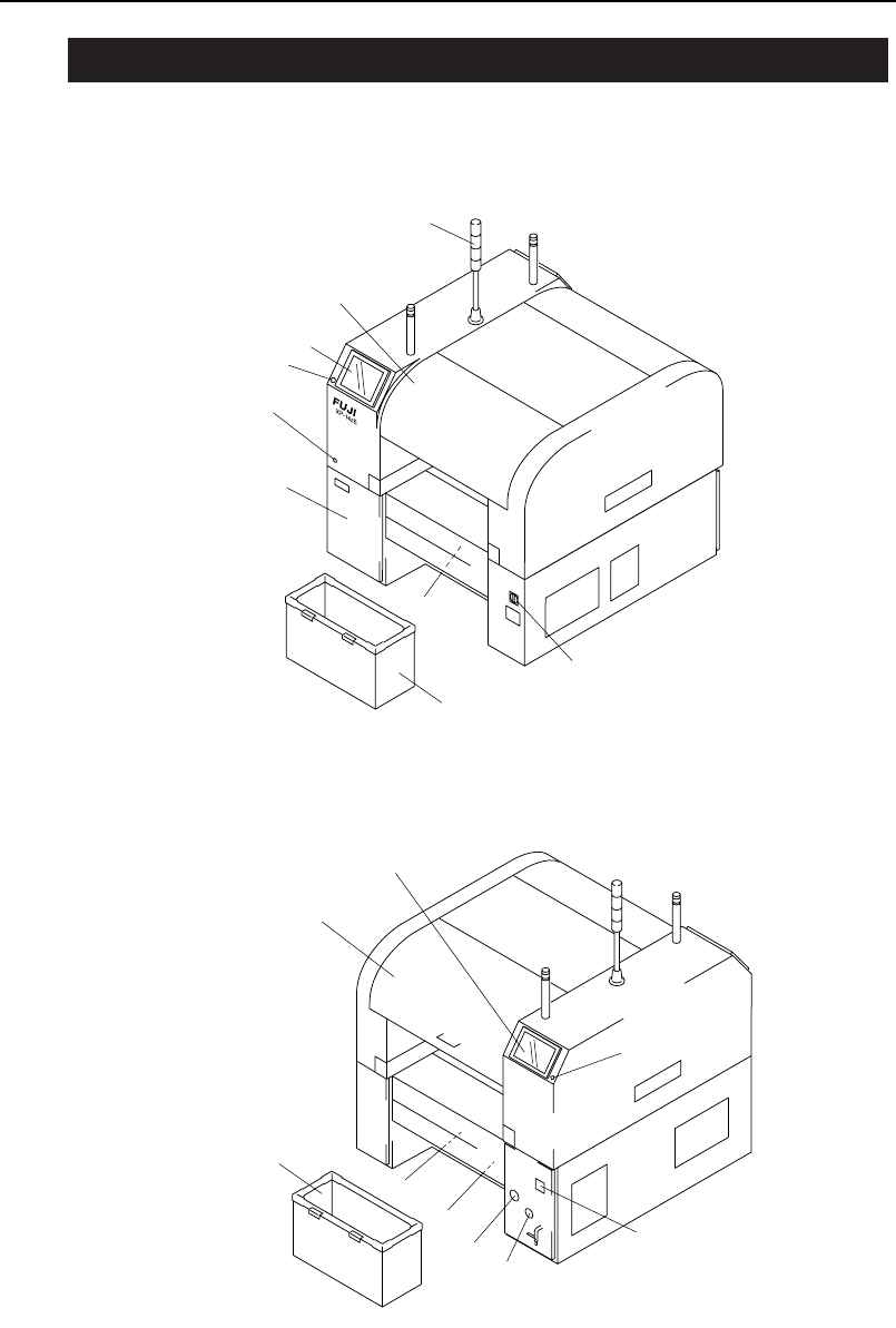
Machine Front (Side 1)
Machine Rear (Side 2)
13
14
15
12
10
11
4
16
XP1ON202a
9
8
7
6
3
4
5
2
1
XP1ON201a
9
1.1 Component Names and Functions
Chapter 1: Machine Configuration
TUT-XP142-1.1E
1-2 XP-142E Operator’s Guide

1. Signal tower
A red, yellow, or blue (green) light will come on or flash on-and-off
depending on the status of the machine during production.
2. Safety Cover 1
3. Operation panel 1
Machine operation is carried out from this panel. Commands are
issued by pressing the buttons on the touch panel.
4. EMERGENCY STOP button
5. Safety switch test button
6. Control box
The machine control system is housed in these boxes.
7. Servo box 1
The servo amps are stored here.
8. Main switch
Set to the ON position to supply power to the machine.
9. Waste tape box
Waste tape is collected after parts are picked up.
10. Operation panel 2
This panel is used to operate the machine from the rear side.
11. Safety Cover 2
12. Servo box 2
The servo amps are stored here.
13. Transformer box
Contains the transformer, servo amplifier, UPS, etc.
14. Vacuum gauge
The vacuum pressure generated by the vacuum pump is displayed
here.
15. Pressure gauge
The supplied air pressure is displayed here.
16. Hour meter
The cumulative number of hours of operation is displayed here.
Chapter 1: Machine Configuration
TUT-XP142-1.1E
1-3XP-142E Operator’s Guide