XP-142E Operator's Guide-TUT-XP142-1.1E.pdf.pdf - 第32页
Setting the Feeders CP-6-series feeders are used on the machine. Refer to the separate CP feeder maintenance manual regarding the procedure for setting parts. <Explanation of the feeder stickers> The sticker that i…
Setting the Scheduled Production Quantity
Specify the number of panels that are scheduled to be produced using the
production program currently selected for use.
Procedure (During production preparation)
1. At the [Main] screen, press [Maintenance A] then [Operation
Settings] to display the operation settings [Select Mode] page.
2. Press the [Scheduled Panels] input field at the right of the
screen to display a ten-key pad. Enter the production quantity
and press [CR].
3. Press [Close] to return to the [Main] screen.
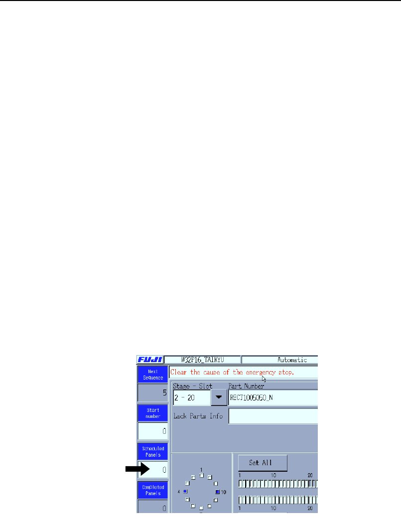
Procedure (During automatic production)
1. Press the [Scheduled Panels] number field at the left of the
[Automatic] screen.
2.
Input the production quantity with the ten-key pad that is
displayed, and then press [CR].
Note: The [Scheduled Panels] quantity can be input from the [Auto] screen
when the quantity is [0] and the READY ON button is flashing.
Production quantity editing is enabled when the field is white.
XP1T3003E
Chapter 3: Preparing for Production
TUT-XP142-1.1E
3-8 XP-142E Operator’s Guide
Setting the Feeders
CP-6-series feeders are used on the machine. Refer to the separate CP feeder
maintenance manual regarding the procedure for setting parts.
<Explanation of the feeder stickers>
The sticker that is affixed to the side of each feeder is printed with a code
indicating the standards for that feeder.
Example: W D 08 04 - - - - -
W: Indicates that the feeder is a CP-6 feeder.
D: This indicates the feeder is a paper tape feeder while "E" represents an
embossed tape feeder.
08: This indicates that a tape with a width of 8 mm can be set on the
feeder.
04: This signifies that the pitch of the feeder is 4 mm.
Notes:
1. When setting feeders in the MFU, be sure that there are no objects (chip
fragments, etc.) between the feeder and the MFU. Remove any foreign
objects from the MFU grooves and from the bottom face of the feeder.
2. Verify that the tape leaf is not deformed.
3. Place the part tapes in their dedicated feeders. A part tape placed in the
wrong feeder may prevent the tape leaf from closing properly.
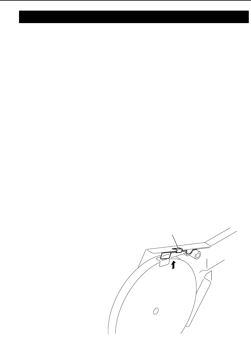
4. Hold the reel retainer up with a clip.
Clip
XP1T3001E
3.3 Part Settings
Chapter 3: Preparing for Production
TUT-XP142-1.1E
3-9XP-142E Operator’s Guide

Attaching the MFU
Procedure
1. Open the safety cover.
2. Slowly push the MFU into the machine to secure it.
3. At the [Main] screen, press [Manual Operation] then [STAGE1
MFU Clamp] or [STAGE2 MFU Clamp]. Press the START
button.
4. Close the safety cover.
Removing the MFU
Procedure
1. At the [Main] screen, press [Manual Operation] then [Retract
Head]. Press the START button.
2. At the [Main] screen, press [Manual Operation] then [STAGE1
MFU Unclamp] or [STAGE2 MFU Unclamp]. Press the START
button.
3. Open the safety cover.
4. Slowly pull the MFU away from the machine to remove it.
Chapter 3: Preparing for Production
TUT-XP142-1.1E
3-10 XP-142E Operator’s Guide