00194103-01.pdf - 第121页
User Manual SIPLAC E F5 HM 5 Tasks on the m achine Software Vers ion SR.408.xx 03/2006 U S Edition 5.6 Avoiding track err ors 121 5.6 A voiding trac k error s 5.6. 1 Gene ral Æ Make sur e that the ar eas aro und th e fee…

5 Tasks on the machine User Manual SIPLACE F5 HM
5.5 Changing the set-up Software Version SR.408.xx03/2006 US Edition
120
5.5 Changing the set-up
5.5.1 Print out the conversion instructions before changing the set-up
Before a change of set-up, print out the conversion instructions on the printer for the SIPLACE Pro
computer as described in the "SIPLACE Pro" manual or in the online help.
5.5.2 What you should note when changing the feeder modules
Æ Handle the feeder modules carefully when you insert them into or remove them from the com-
ponent feeder table. Make sure that the feeder modules do not bump against the CO table
edges.
Æ Vacuum the supporting surfaces of the feeders and clean the surface of the component feeder
table when necessary according to the instructions in the Preventive Maintenance Manual.
CAUTION
Avoid removing components from the magnetic rail of the component table with your fingers.
You may hurt yourself with tiny splinters of metal. 5
Æ Remove loose components using a brush or a vacuum cleaner with a suitable nozzle.

User Manual SIPLACE F5 HM 5 Tasks on the machine
Software Version SR.408.xx 03/2006 US Edition 5.6 Avoiding track errors
121
5.6 Avoiding track errors
5.6.1 General
Æ Make sure that the areas around the feeder modules are clean and that there are no loose com-
ponents in the feeder area or under the feeder modules.
Æ Ensure that the supporting surfaces of the feeder modules, and particularly the magnetic rails
of the component feeder tables, are clean and level.
Æ Refill promptly with components.
Æ Splice the tapes early. This generally means that you are to prepare the splicing material when
there is still approximately 1.5 m of tape on the reel.
Æ Handle the feeder modules carefully when you insert them into or remove them from the com-
ponent feeder table as these are high-precision devices.
Æ Close the pick-up window on the feeder module. You may damage the module when it is open.
Æ Check that the pick-up position is set correctly for the components on the S feeder modules.
Æ Check to see if all the plugs of the S feeder modules are plugged in to the correct sockets.
5.6.2 Avoiding track errors with the tape container
Æ Insert the separating plates correctly (see Fig. 5.3 - 2).
Æ Tape reels with a diameter of 15" (381 mm) or more should be stored on spindles.
Æ Make sure to use the support for the middle tape reel on 3 x 8 mm feeder modules (see Section
6.3.4
, page 161).
5 Tasks on the machine User Manual SIPLACE F5 HM
5.6 Avoiding track errors Software Version SR.408.xx03/2006 US Edition
122
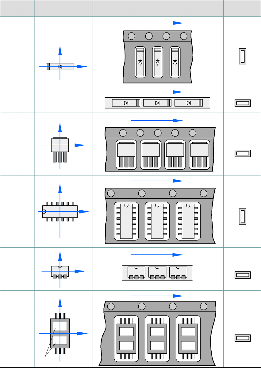
5.6.3 Component coordinate system and pick-up angle
5
Fig. 5.6 - 1 Position of the component and its pick-up angle
Special
component
Stick maga-
zine:
Chip-
components
with polarity
0402
2220
The anode must be
aligned with the +X
coordinate.
Package form Coordinate system
Position in the feeder
Pick-up angle/
nozzle angle
Tape:
SOT 23
Stick maga-
zine:
Tape:
Tape:
SO-IC
DIL-IC
SOT 194
Tape:
Holes
Y
X
Y
X
Y
X
Y
X
Y
X
90°
90°
0°
90°
-90°
0°