00194103-01.pdf - 第60页
2 Operational safety User Manual SIP LACE F5 HM 2.7 Disabling the compressed air supply and discharging the pressure Software Version SR.408.xx 03/2006 US Edition 60 The compr essed ai r working pressure is set to 0.52 M…
User Manual SIPLACE F5 HM 2 Operational safety
Software Version SR.408.xx 03/2006 US Edition 2.7 Disabling the compressed air supply and discharging the pressure
59
2.7 Disabling the compressed air supply and discharg-
ing the pressure
2
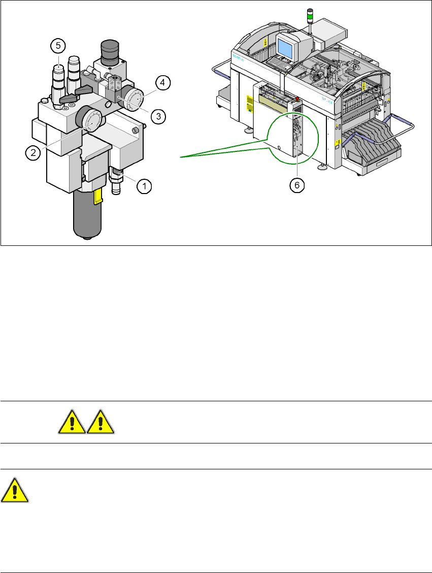
Fig. 2.7 - 1 Compressed air unit on the placement machine
WARNING NEVER detach compressed air lines while they are still pressurized. 2
CAUTION 2
When the machine is switched on, do not use the stop valve to interrupt the compressed air supply
for more than 30 minutes. If you need to shut off the pneumatic system for longer in order to carry
out preventive maintenance or servicing work, you must switch the placement system off at the
main switch and disconnect it from the power supply. 2
(1) Shutoff valve lever in the CLOSED position
(2) Working pressure gauge
(3) Solenoid valve for venting the tape cutter during an EMERGENCY STOP
(4) Pressure gauge for the PCB stopper working pressure
(5) Compressed air supply, gantry 1
(6) Position of the compressed air unit

2 Operational safety User Manual SIPLACE F5 HM
2.7 Disabling the compressed air supply and discharging the pressure Software Version SR.408.xx 03/2006 US Edition
60
The compressed air working pressure is set to 0.52 MPa (5.2 bar). It may fluctuate between 0.51
MPa (5.1 bar) and 0.53 MPa (5.3 bar). The position of the compressed air unit is indicated by pos.
6 in Fig. 2.7 - 1
. The compressed air supply to the machine can be interrupted using the shutoff
valve (pos. 1 in Fig. 2.7 - 1
). 2
– You must remove the cover plate to use the shutoff valve.
– Turn the lever on the shutoff valve (pos. 1 in Fig. 2.7 - 1
) from the vertical to the horizontal po-
sition.
– Watch the working pressure gauge (pos. 2 in Fig. 2.7 - 1
) and the pressure gauge for the com-
pressed air supply to the stopper (pos. 4 in Fig. 2.7 - 1
). When the automatic placement system
is switched on, the pressure discharges to 0 MPa (0 bar) within 1 minute.
User Manual SIPLACE F5 HM 2 Operational safety
Software Version SR.408.xx 03/2006 US Edition 2.8 Energy state of the machine after switching off at the main switch
61
2.8 Energy state of the machine after switching off at
the main switch
DANGER
Automatic placement systems from the SIPLACE family are powered with 3 x 400 V or 3 x
208 VAC (U.S.A. version) ± 5 %, 50/60 Hz mains voltage. This means that parts of the system
carry potentially fatal voltages - even when switched off at the main switch. Death, serious injury
or considerable damage may result if these automatic placement systems are handled incorrectly.
Always follow the applicable accident prevention and DIN regulations (particularly EN 60204,
part 1). The guards over the control and servo units must ONLY be opened by appropriately qual-
ified and trained personnel. 2
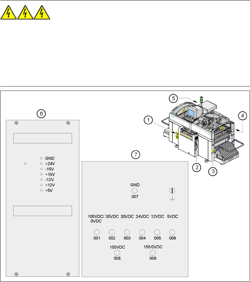
Fig. 2.8 - 1 Location of the control unit, servo unit, main switch, service socket and compressed air unit in the place-
ment machine
(1) Main switch Q1 (2) Compressed air unit
(3) Service socket (4) Servo unit
(5) Control unit (6) Power supply unit in the control unit
(7) Measuring unit, servo unit 2
permanent
switchable