00194103-01.pdf - 第180页
7 Options User Manual SIP LACE F5 HM 7.2 Nozzle changer for the 6-segment Co llect&Place head Software Version SR .408.xx 03/2006 US E dition 180 7 Fig. 7.2 - 1 Nozzle ch anger for the 6-seg ment Collect&Pla ce h…

User Manual SIPLACE F5 HM 7 Options
Software Version SR.408.xx 03/2006 US Edition 7.2 Nozzle changer for the 6-segment Collect&Place head
179
7.2 Nozzle changer for the 6-segment Collect&Place
head
7.2.1 Overview
A nozzle changer for the 6-segment Collect&Place head may be installed to the left of the PCB
conveyor without losing any locations. This enables the nozzle configuration to be changed
quickly, thus allowing the Collect&Place head to be quickly adapted to the needs of the place-
ment process.
The nozzle changer consists of at least one, and up to five magazines, each with twelve nozzle
garages (see Fig. 7.2 - 1
). The magazines are seated on a common support. Each magazine is
centered using two parallel pins and fixed in place with a spring hook.
Magazines with 9xx or 8xx nozzle types can be set up. The magazines can be arranged as
required.
7.2.2 Technical data - Nozzle changer for the 6-segment Collect&Place head
7
Nozzle changer for the 6-segment Collect&Place head
Dimensions (length x width x height) 575 x 70 x 60 mm³
Number of nozzle garages min. 6 / max. 30
Nozzle types 8 xx, 9 xx
Opening and closing the plate < 200 ms
Capacity of the reject bin approx. 50 nozzles from the 9xx type,
approx. 5 nozzles from the 8xx type
Pneumatic circuit Compressed air line 5.2 bar
7 Options User Manual SIPLACE F5 HM
7.2 Nozzle changer for the 6-segment Collect&Place head Software Version SR.408.xx 03/2006 US Edition
180
7
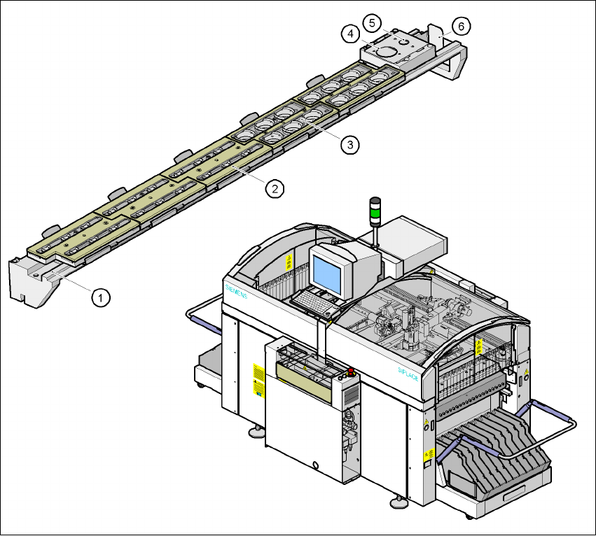
Fig. 7.2 - 1 Nozzle changer for the 6-segment Collect&Place head, overview
(1) Nozzle changer, base
(2) 9xx nozzle magazine
(3) 8xx nozzle magazine
(4) 8xx nozzle discarding device
(5) 9xx nozzle discarding device
(6) Reject bin for discarded nozzles
User Manual SIPLACE F5 HM 7 Options
Software Version SR.408.xx 03/2006 US Edition 7.2 Nozzle changer for the 6-segment Collect&Place head
181
7
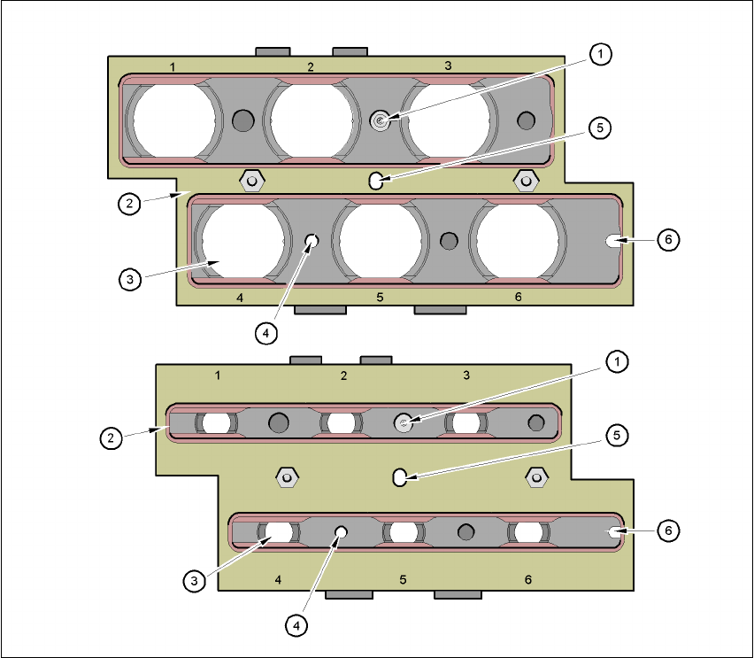
Fig. 7.2 - 2 Overview - Magazine and nozzle garage
(1) Positioning fiducial
(2) Locking plate
(3) 9xx or 8xx nozzle garage
(4) Hole for the parallel pin for centering the magazines
(5) Hole for the parallel pin of the slide mechanism
(6) Slot for the parallel pin for centering the magazines
7.2.3 Mode of operation
The nozzles are seated in nozzle garages and are held in place by a movable locking plate. The
locking plate can be moved 6 mm by a pneumatic cylinder. All the nozzles are either clamped or
released, depending on the position of the plate. The default position of the locking plate, i.e. if
there is no nozzle change in progress, is "closed".