00194103-01.pdf - 第79页
User Manual SIPLAC E F5 HM 3 Technical data Software Vers ion SR.408.xx 03/2006 U S Edition 3.6 Dimens ions and weight of the plac ement system 79 3.6.4 Maneuvring radius of t he component t rolley 3 Fig. 3.6 - 3 M aneuv…
3 Technical data User Manual SIPLACE F5 HM
3.6 Dimensions and weight of the placement system Software Version SR.408.xx 03/2006 US Edition
78
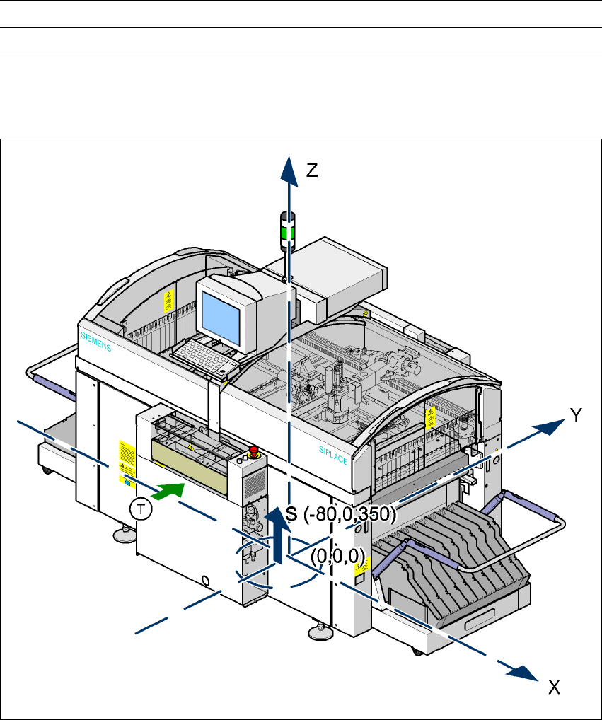
3.6.3 The placement system’s center of gravity
3
Fig. 3.6 - 2 The placement system’s center of gravity
X coordinate - 80 mm
Y coordinate 0 mm
Z coordinate 350 mm high
T PCB transport direction 3
These center of gravity coordinates relate to placement systems with a PCB transport height of
830 mm. 3
Admissible load per unit area on foundation 1000 kg/m² min.
Load per unit area on mounting feet 4.42 kg/cm²
User Manual SIPLACE F5 HM 3 Technical data
Software Version SR.408.xx 03/2006 US Edition 3.6 Dimensions and weight of the placement system
79
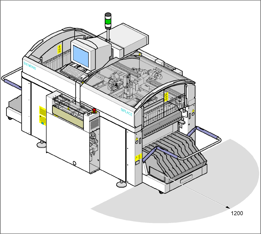
3.6.4 Maneuvring radius of the component trolley
3
Fig. 3.6 - 3 Maneuvring radius of the component trolley in millimeters
3 Technical data User Manual SIPLACE F5 HM
3.6 Dimensions and weight of the placement system Software Version SR.408.xx 03/2006 US Edition
80
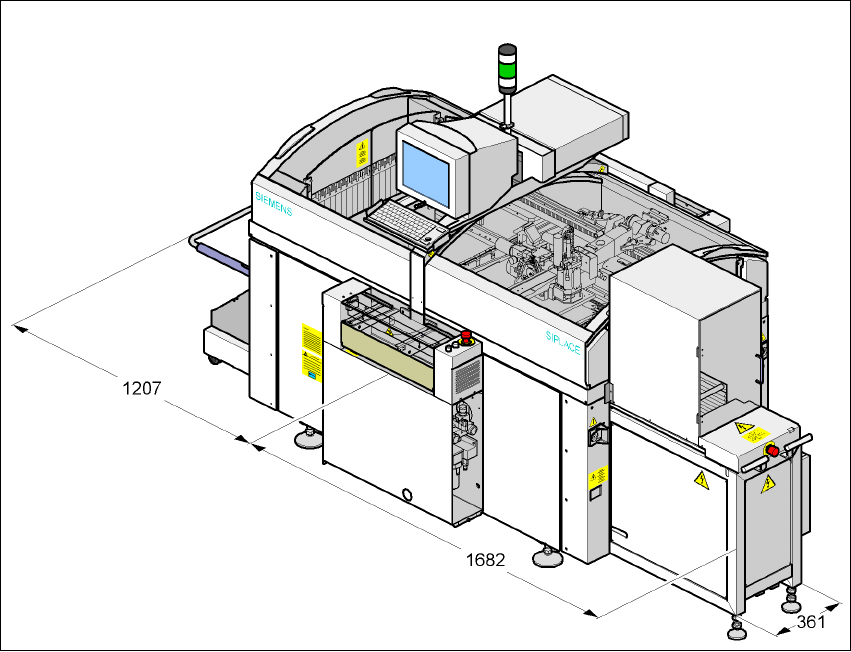
3.6.5 Dimensions of the placement machine with WPC and component trolley
3
Fig. 3.6 - 4 Dimensions of the placement machine with WPC and component trolley in millimeters
3
3