00194103-01.pdf - 第43页
User Manual SIPLAC E F5 HM 2 Operational safety Software Vers ion SR.408.xx 03/2006 U S Edition 2.4 Safety instructions for operat ing the machine 43 2.4 Safety instructions fo r operating the machine 2.4.1 Safety instru…
2 Operational safety User Manual SIPLACE F5 HM
2.3 Laser classification Software Version SR.408.xx 03/2006 US Edition
42
2
Warning label (number per WPC: 4)
2
2
2
2.3 Laser classification
PLEASE NOTE: 2
Modules in laser classes 1 and 1M are not identified.
2.3.1 Laser class 1
2
2
2.3.2 Laser class 2
The following modules are assigned to laser class 2:
– PCB barcode scanner
– Coplanarity laser module
2
2
2
2
DANGEROUS VOLTAGES!
The identified parts are under mains voltage.
Disconnect the machine from the main power supply before ser-
vicing it!
NAFTA region: RISK OF ELECTRIC SHOCK OR BURN!
All installed camera systems and the whole machine when ready
for operation are assigned to laser class 1.
The laser classes are determined as per DIN EN 60825-1:2001.
2
Laser radiation
Do not look into beam!
User Manual SIPLACE F5 HM 2 Operational safety
Software Version SR.408.xx 03/2006 US Edition 2.4 Safety instructions for operating the machine
43
2.4 Safety instructions for operating the machine
2.4.1 Safety instructions on docking and undocking the component trolley
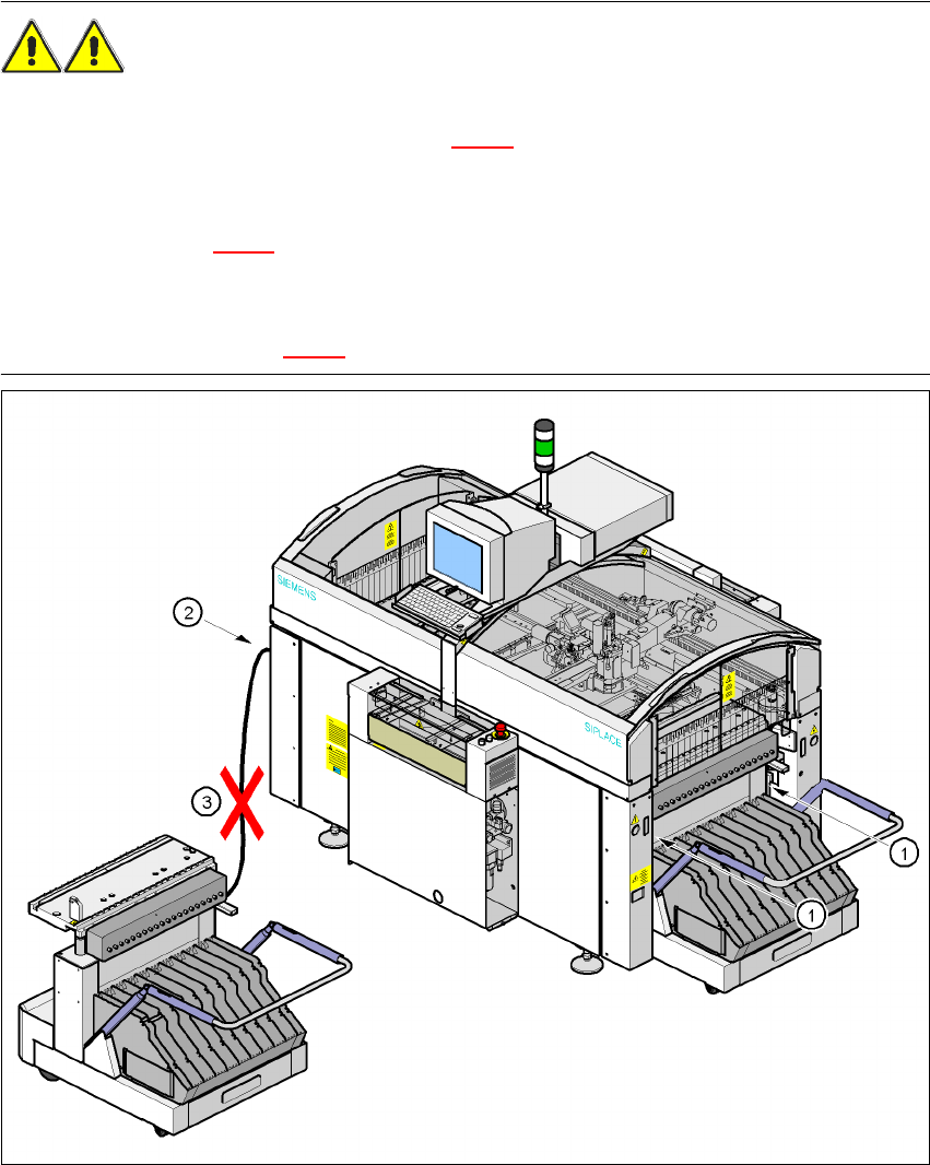
WARNING 2
Æ Never reach into the gap between the component trolley and the placement system frame
while the machine is running (item 1 in Fig. 2.4 - 1
).
Æ Always check that the component trolley is docked on the placement system before connecting
or disconnecting the power cable for the component trolley at the socket on the placement sys-
tem (item 2 in Fig. 2.4 - 1
).
Æ NEVER connect the connecting cable for the component trolley to the socket on the placement
system and then operate the component trolley outside the machine via the compressed air
control unit (item 3 in Fig. 2.4 - 1).
Fig. 2.4 - 1 Safety instructions on the component trolley
2 Operational safety User Manual SIPLACE F5 HM
2.4 Safety instructions for operating the machine Software Version SR.408.xx 03/2006 US Edition
44
2.4.2 Safety instructions for lowering the component table bed
WARNING DANGER OF CRUSHING 2
When lowering the component table bed, never reach into the gap between the feeders and the
used tape channel. 2
2.4.3 Safety instructions for changing the table height of component trolleys
WARNING DANGER OF CRUSHING 2
Remove all the feeders from the component table bed, before you adjust the table height of the
component trolley.
Act with considerable care during the conversion process because the table bed is very heavy.
Conversion of the component trolley to other PCB transport heights is described in Section 4.3
on
page 107. 2