00194103-01.pdf - 第154页
6 Component handling User Manual S IPLACE F5 H M 6.2 Technical dat a for the S feeder modules Software Version S R.408.xx 03/2006 US Edition 154 PLEAS E NOTE 6 The suppor t for the w affle-pack magazi ne must on ly be pl…
User Manual SIPLACE F5 HM 6 Component handling
Software Version SR.408.xx 03/2006 US Edition 6.2 Technical data for the S feeder modules
153
6.2.18 Waffle-pack tray holder
The waffle-pack tray holder allows components to be picked up from individual waffle-pack trays.
The waffle-pack trays are changed manually.
6
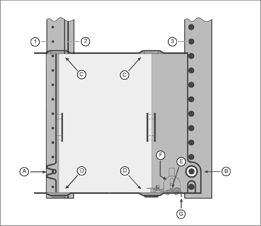
Fig. 6.2 - 18 Installation
(1) Centering pins
(2) Magnetic rail
(3) Centering ball
The waffle-pack tray holder is placed on the component table as for a feeder module. There are
two different versions of the support, the only difference being the width.
Holder for large waffle tray (260x360mm², fills 9 locations)
item no. 00116430-01 and 6
Holder for small waffle-pack trays (136x360mm², fills 5 locations)
item no. 00116432-01 6
6
6 Component handling User Manual SIPLACE F5 HM
6.2 Technical data for the S feeder modules Software Version SR.408.xx 03/2006 US Edition
154
PLEASE NOTE 6
The support for the waffle-pack magazine must only be placed on the right-hand side of the SI-
PLACE F5 HM. It can only be positioned so that the right edge fills no more than track 73. 6
6.2.18.1 Assembly
Æ Insert the front side of the waffle-pack tray holder into the associated centering pin (A in Fig.
6.2 - 18
).
Æ Then position the hole on the rear side of the waffle-pack tray holder onto the centering ball on
the component feeder table (B in Fig. 6.2 - 18
).
Æ Make sure the waffle-pack tray is resting securely on the component feeder table.
Æ Position one side of the waffle-pack tray carrier in the mounting (C in Fig. 6.2 - 18). Then press
the other side into the mounting (D in Fig. 6.2 - 18
).
Æ Slide the waffle-pack tray up against the stop (E in Fig. 6.2 - 18).
Æ Secure the waffle-pack tray carrier by pressing the thrust pad (F in Fig. 6.2 - 18) downwards.
Æ To remove the waffle-pack tray carrier, press the thrust pad once more.
PLEASE NOTE
Using the holder for small waffle-pack trays (136mm) a waffle-pack tray (JEDEC or CENELEC
waffle-pack tray) can be fitted directly to the holder, in other words, without a waffle-pack tray car-
rier being used. Replace the retainer (G in Fig. 6.2 - 18).
WARNING
All locations must be equipped with feeder modules in order to guarantee operational reliability.
If there are not enough feeder modules available, unassigned locations should be fitted with a
hand guard (dummy feeder module). When a waffle-pack tray holder is set up, the remaining
locations have to be protected again with a hand guard.
6.2.18.2 Changing the retainer
Æ Hold the retainer (G in Fig. 6.2 - 18) firmly. Press the thrust pad downwards (F in Fig. 6.2 - 18)
and remove the retainer by pressing it out sideways.
6.2.18.3 Data entry
Define the waffle-pack trays as described in the SIPLACE Pro operating instructions.
User Manual SIPLACE F5 HM 6 Component handling
Software Version SR.408.xx 03/2006 US Edition 6.2 Technical data for the S feeder modules
155
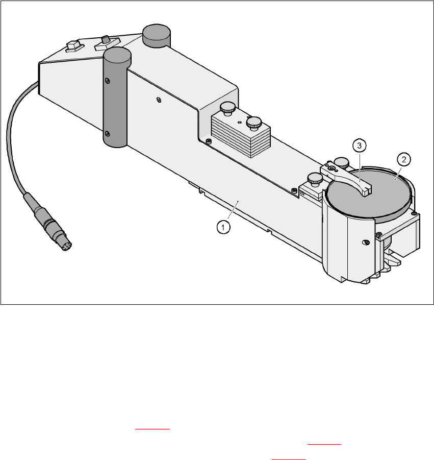
6.2.19 Dip module
6
Fig. 6.2 - 19 Dip module
(1)Dip module
(2)Rotating plate
(3)Squeegee
6.2.19.1 Principle of dip fluxing
The dip module (item 1 in Fig 6.2 - 19) is used to wet flip-chip and CSP components with flux or
conductive adhesive. The flux holder is a rotating plate (item 2 in Fig. 6.2 - 19
) on which a thin film
of flux (e.g. 40 µm) is created with a squeegee (item 3 in Fig. 6.2 - 19
). This method is particularly
suitable for highly viscous (honey-like) fluxes. The amount of flux required for the process is re-
duced to a minimum coating thickness since only the undersides of the bumps have to be wetted.
The dip module is suitable for all placement heads. It is regarded as a standalone type of conveyor
by the set-up optimization. There is no limit to the number of dip modules at the individual loca-
tions.