00194103-01.pdf - 第128页
5 Tasks on the machine User Manual S IPLACE F5 HM 5.8 Docking the component trolley in or out Software V ersion SR.408.xx03/2006 US Edition 128 5.8.3 Docking in the component trolley PLEAS E NOTE 5 Shorten th e compone n…

User Manual SIPLACE F5 HM 5 Tasks on the machine
Software Version SR.408.xx 03/2006 US Edition 5.8 Docking the component trolley in or out
127
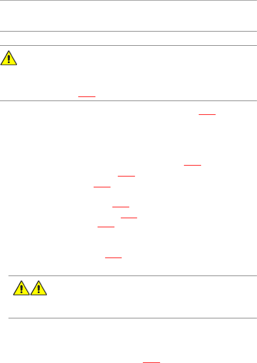
(8) Holes for the centering pins
(9) Centering pin for the component table bed
(10) Contact surfaces for the component table bed (right and left)
(11) Horizontal tensioners
(12) Movable cover that ensures that the power supply and control cables are plugged in and
removed in the correct order.
5
5.8.2 Docking out the component trolley
Æ
Click on the STOP PROCESSING PCB icon in the MAIN VIEW menu.
Æ The PCB in progress will be completed. The icons of the SINGLE FUNCTIONS menu will then
be activated.
Æ Click on the icon SINGLE FUNCTIONS GANTRY.
Æ Click on the GANTRY FUNCTIONS icon.
Æ From this menu, click on the GO TO SET-UP POSITION button.
Æ All the placement heads will move across the PCB conveyor to prevent them being damaged
when the component trolley is changed.
Æ Open protective cover of the selected gantry.
Æ Open the side screens.
Æ Open the horizontal tensioners (item 11 in Fig. 5.8 - 2)
Æ Pull the two actuating tubes (item 6 in Fig. 5.8 - 2) towards you at the same time and lift up the
bracket (item 7 in Fig. 5.8 - 2
). Thus you will lock the raised component table bed in its top end
position.
WARNING DANGER OF CRUSHING 5
When raising the component table bed, never reach into the gap between the feeders and
the used tape channel. 5
Æ Hold down the button (item 5 in Fig. 5.8 - 2) for raising the component table bed (item 4 in Fig.
5.8 - 2
) until the component table bed locks into its top end position.
Æ Unplug the component trolley power cable (item 2 in Fig. 5.8 - 2).
Æ Move the cover (item 12 in Fig. 5.8 - 2) sideways until you can unplug the control cable (item 1
in Fig. 5.8 - 2
).
Æ Unplug the component table control cable (item 1 in Fig. 5.8 - 2).
Æ Unplug the connector for the compressed air supply (item 3 in Fig. 5.8 - 2).
Æ Remove the component trolley.
5 Tasks on the machine User Manual SIPLACE F5 HM
5.8 Docking the component trolley in or out Software Version SR.408.xx03/2006 US Edition
128
5.8.3 Docking in the component trolley
PLEASE NOTE 5
Shorten the component tapes on the front end of the S feeder to approximately 1 cm before you
dock in the component trolley.
CAUTION 5
Æ Check that the placement head is outside the range of the component trolley.
Æ When docking in the component trolley, ensure that the table bed is in its top end position and
the bracket (item 7 in Fig. 5.8 - 2) is folded up.
Æ Check to see whether the left and right contact surfaces (Item 10 in Fig. 5.8 - 2) for the compo-
nent table bed are clean.
Æ Check to see that the contact surfaces on the underside of the component table bed are also
clean.
Æ CAREFULLY push the component trolley into the placement system.
Æ Attach the connector for the compressed air supply (item 3 in Fig. 5.8 - 2).
Æ Connect the control cable (item 1 in Fig. 5.8 - 2).
Æ Move the cover (item 12 in Fig. 5.8 - 2) over the control cable plug to expose the power supply
socket.
Æ Plug in the power cable (item 2 in Fig. 5.8 - 2) for the component trolley.
Æ Pull the two actuating tubes (item 6 in Fig. 5.8 - 2) towards you at the same time and then lower
the trolley bracket (item 7 in Fig. 5.8 - 2
) in order to be able to lower the component trolley.
Æ Check that the centering holes in the component table bed lie precisely over the centering pins
of the placement system.
Æ Hold down the button (item 5 in Fig. 5.8 - 2) until the component table bed locks into its top end
position.
WARNING DANGER OF CRUSHING 5
When lowering the component table bed, never reach into the gap between the feeders and
the used tape channel. 5
Æ Release the button. The component table bed will descend.
Æ Ensure that the centering pins engage in the centering holes in the component table bed and
that the component table bed is fully lowered.
Æ Lock the two horizontal tensioners (item 11 in Fig. 5.8 - 2).

User Manual SIPLACE F5 HM 5 Tasks on the machine
Software Version SR.408.xx 03/2006 US Edition 5.9 Operating status indicator lamp
129
Æ Close the side screens and protective cover.
Æ Press the Start button to start the placement system.
5
5
5.9 Operating status indicator lamp
The sequence of colors of the indicator lamp is white (L1) - green (L2) - white (L3). These lamps
are used to signal operating statuses and malfunctions of the placement system.
5.9.1 Description of the functions
Fig. 5.9 - 1 Operating status indicator lamp
5.9.2 General operating statuses
–
Operating status lamp (green) on continuously
The placement system is in service.
–
Operating status lamp (green) flashes
The placement system is waiting for a PCB on the input belt or the placement system is waiting
until the output belt is free.
–
Upper fault indicator lamp L1 (white) flashes
One or more tracks are empty on the right-hand side of the placement system. The placement
system continues to place any remaining components.
–
Lower fault indicator lamp L3 (white) flashes
One or more tracks are empty on the left-hand side of the placement system. The placement
system continues to place any remaining components.
–
Upper fault indicator lamp L1 (white) on continuously - operating status lamp L2 (green) off
5
L1: Fault indicator lamp (white)
L2: Operating status lamp (green)
L3: Fault indicator lamp (white)