00194103-01.pdf - 第218页
7 Options User Manual SIP LACE F5 HM 7.13 PCB support Software Version SR.408.xx 03/2006 US Edition 218 7.13 PCB support Item no. 003 02454-xx Wide boar ds tend to de flect durin g placeme nt such tha t, under certain ci…
User Manual SIPLACE F5 HM 7 Options
Software Version SR.408.xx 03/2006 US Edition 7.12 SIPLACE productivity lift
217
7.12.3 Advantages of the productivity lift
The productivity lift can raise the productivity of a line overall because it increases the placement
rates of the machines on the line.
7
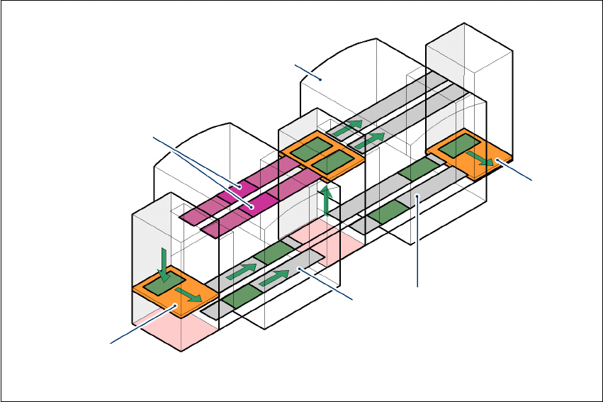
Fig. 7.12 - 3 Productivity lift – Avoiding stoppages
If lines are connected in parallel, individual machines may fail without bringing the entire line to a
standstill. It is also possible access individual machines while the rest of the line continues placing
without interruption.
This could be for
– process-related investigations or test operation
– programming PCB fiducials, package forms or test placements
– maintenance or repairs
– operating errors, such as not splicing tapes on in good time or missing components.
Another advantage is that the line can be reconfigured as required using the software, without
having to reset the machines.
Conveyor section, processing
Placement machine
Horizontal
and vertical lift
Underfloor conveyor
Track change
7 Options User Manual SIPLACE F5 HM
7.13 PCB support Software Version SR.408.xx 03/2006 US Edition
218
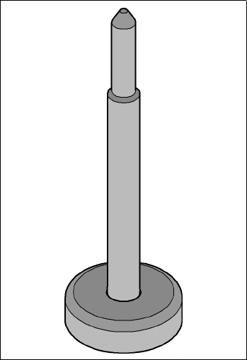
7.13 PCB support
Item no. 00302454-xx
Wide boards tend to deflect during placement such that, under certain circumstances, the compo-
nents can no longer be placed with the desired accuracy. Highly curved PCBs also affect the
placement accuracy. This problem can be easily rectified by fitting PCB supports on the lifting ta-
ble.
7
Fig. 7.13 - 1 PCB support

User Manual SIPLACE F5 HM Index
03/2006 US Edition
219
Index
12 mm S tape feeder module for capacitors based
on powdered metal
model C/D
139
model E
140
12/16 mm S tape feeder module
138
12-segment Collect&Place head
72
angular accuracy
72
component vision module
88
description
89
motor for "Reject" valve adjustment drive
88
placement accuracy
72
star motor
88
star with 12 sleeves
88
structure
88
technical data
89
turning station
88
Z axis drive
88
24/32 mm S DP tape feeder module for deep pock-
ets
142
24/32 mm S tape feeder module
141
3 x 8 mm S tape feeder module
136
3 x 8 mm S tape feeder module for 0201/0402 com-
ponents
137
44 mm S DP tape feeder module for deep pockets
144
44 mm S tape feeder module
143
56 mm S DP tape feeder module for deep pockets
146
56 mm S tape feeder module
145
6/12-segment Collect&Place head
69
6-segment Collect&Place head
72
angular accuracy
72
description
91
motor for "Reject" valve adjustment drive
90
placement accuracy
72
standard component vision module
90
star motor
90
star with 6 sleeves
90
technical data
91
turning station
90
Z axis drive
90
6-segment Collect&Place head with DCA camera
DCA vision module
211
description
212
motor for "Reject" valve adjustment drive
211
star motor
211
star with 6 sleeves
211
technical data
212
turning station
211
Z axis drive
211
72 mm S tape feeder module
147
8 mm S II tape feeder module
135
88 mm S tape feeder module
148
A
abbreviations 19
admissible load per unit area on foundation
78
ambient factors, permitted
76
asynchronous transport mode
description
99
function
99
atmospheric humidity
77
authorized accessories
24
avoiding track errors
121
B
bulk case feeder module 150
C
C&P 19
C&P12
19
C&P6
19
carrying out a set-up check
112
carrying out a walk-through inspection
113
center conveyor
96
center of gravity coordinates
78
centering ball
154
ceramic substrate centering
192
fiducial recommendation
195
fiducial shape
195
fiducial structure
196
general
192
maintenance
193
technical data
194
changing shift
112
changing the retainer
154
changing the set-up
120