00194103-01.pdf - 第97页
User Manual SIPLAC E F5 HM 3 Technical data Software Vers ion SR.408.xx 03/2006 U S Edition 3.11 PCB sing le conveyor 97 The con veyor bel ts are driven by DC motors . The lifting table i n the cent er conv eyor area cla…
3 Technical data User Manual SIPLACE F5 HM
3.11 PCB single conveyor Software Version SR.408.xx 03/2006 US Edition
96
3.11 PCB single conveyor
3.11.1 Structure
The placement system is supplied with a single conveyor as standard. A dual conveyor is avail-
able as an option. The left or the right side of the PCB conveyor can be used as the stationary
side, as required. 3
3
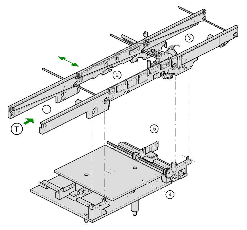
Fig. 3.11 - 1 Structure of the PCB single conveyor
(1) Input conveyor (2) Center conveyor
(3) Output conveyor (4) Lifting table
(5) Width adjustment T Direction of PCB transport 3

User Manual SIPLACE F5 HM 3 Technical data
Software Version SR.408.xx 03/2006 US Edition 3.11 PCB single conveyor
97
The conveyor belts are driven by DC motors. The lifting table in the center conveyor area clamps
the PCBs. The width of the PCB conveyor can be adjusted either via the menu or the SIPLACE
Pro computer. 3
3.11.2 Technical data - single conveyor
3
3
PCB format 50 x 50 mm² up to 460 x 460 mm²
2" x 2" up to 18" x 18"
Optional: up to 508 x 460 mm²
up to 20" x 18"
PCB thickness 0.5 up to 4.5 mm
Max. PCB warpage up: 4.5 mm - PCB thickness
down: 0.5 mm + PCB thickness
Clearance on PCB underside 25 mm (standard), 40 mm (option)
PCB transport height 830 mm ± 15 mm (standard)
900 mm ± 15 mm (optional)
930 mm ± 15 mm (optional)
950 mm ± 15 mm (SMEMA: optional)
Fixed conveyor side Right (standard), left (optional)
Type of interface Siemens (standard), (SMEMA, option)
Component-free PCB handling
edge
3 mm
PCB changeover time 2.5 s
3 Technical data User Manual SIPLACE F5 HM
3.12 PCB dual conveyor Software Version SR.408.xx 03/2006 US Edition
98
3.12 PCB dual conveyor
3.12.1 Structure
The conveyor belts are driven by DC motors. There is a lifting table for holding the PCBs in each
processing area. The width of the PCB conveyor can be adjusted either via the menu or using
the SIPLACE Pro computer.
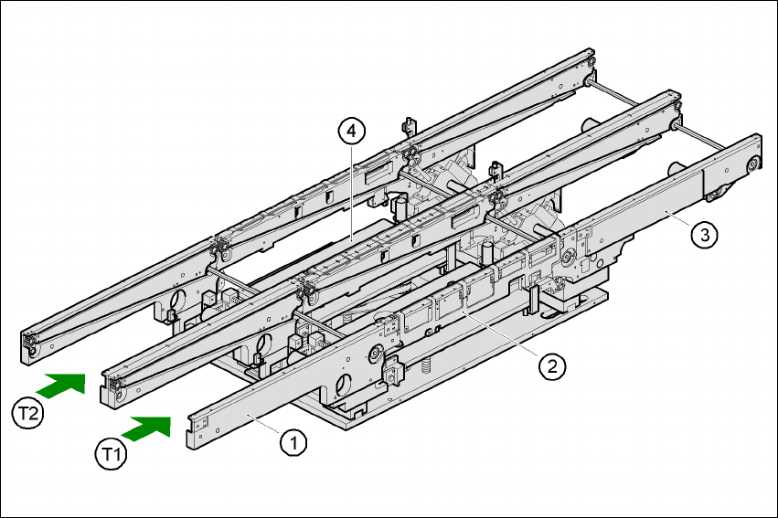
Fig. 3.12 - 1 Structure of the dual conveyor
3.12.2 General
As the name suggests, the dual conveyor has two transport tracks, which are electrically and
mechanically independent of one another. In the Standard version, the right-hand side is the
fixed side. There is another version, however, in which the left-hand side is the fixed side.
(1) Input belt (2) Center belt
(3) Output belt (4) Lifting table
T1 Conveyor track 1 T2 Conveyor track 2