00194103-01.pdf - 第72页
3 Technical data User Manual S IPLACE F5 H M 3.2 Performanc e data Software Vers ion SR.408.xx 03/2006 US Edition 72 3.2 Performanc e dat a 3.2.1 T echnica l dat a - Ma chine overvie w 3 * The SIPLACE F5 HM can be equipp…
User Manual SIPLACE F5 HM 3 Technical data
Software Version SR.408.xx 03/2006 US Edition 3.1 Description of the machine
71
3.1.0.1 Head modularity concept (Head Modularity)
The abbreviation HM in the designation of the SIPLACE F5HM placement system stands for
Head Modularity. 3
Changing from a 6-segment to a 12-segment Collect&Place head and vice versa will enable the
system to be quickly adapted to the requirements of individual placement jobs. 3
3
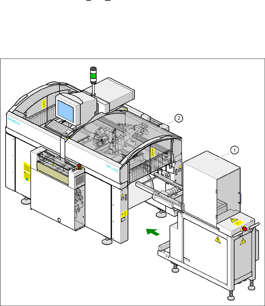
Fig. 3.1 - 2 SIPLACE F5 HM overall view with waffle-pack changer
(1) Waffle-pack changer
(2) SIPLACE F5 HM

3 Technical data User Manual SIPLACE F5 HM
3.2 Performance data Software Version SR.408.xx 03/2006 US Edition
72
3.2 Performance data
3.2.1 Technical data - Machine overview
3
* The SIPLACE F5 HM can be equipped to place 0201 components.
(Please consult the factory if you require this.)
** With the DCA package only
*** With the flip chip component vision module for the Pick & Place head only
3
3
Method Pick&Place / Collect &Place
Component range from 0.6 x 0.3 mm² (0201*) to 55 x 55 mm²
Max. placement rate
6-segment Collect&Place head
12-segment Collect&Place head
Pick&Place head
8,500 comp./h
11,000 comp./h
1,800 comp./h
6-segment Collect&Place head
Angular accuracy
Placement accuracy
± 0.225°/ 3 σ, ± 0.30°/ 4 σ, ± 0.45°/ 6 σ
± 52.5 µm / 3 σ, 70 µm / 4 σ, 105 µm / 6 σ
± 45 µm / 3 σ, 60 µm / 4 σ, 90 µm / 6 σ **
12-segment Collect&Place head
Angular accuracy
Placement accuracy
± 0.525°/ 3 σ, ± 0.70°/ 4 σ, ± 1.05°/ 6 σ
± 67.5 µm / 3 σ, 90 µm / 4 σ, 135 µm / 6 σ
Pick&Place head
Angular accuracy
Placement accuracy
± 0.053°/ 3 σ, ± 0.07°/ 4 σ, ± 0.105°/ 6 σ
± 37.5 µm / 3 σ, 50 µm / 4 σ, 75 µm / 6 σ
± 30 µm / 3 σ, 40 µm / 4 σ, 60 µm / 6 σ ***
PCB format (LxW)
Single conveyor
Dual conveyor
50 x 50 mm² to 508 x 460 mm²
(2" x 2" up to 20" x 18")
(optional: up to 610 mm length)
50 x 50 mm² up to 460 x 216.5 mm²
(2" x 2" up to 18 x 8.5" )
Feeder capacity 40 feeder module locations
Component supply
Feeder module types
CO trolley, waffle-pack changer, waffle-pack tray holder,
component tapes, stick magazines, bulk cases
Operating system Microsoft Windows XP / RMOS
Connection Inline or stand alone
Space required 4 m² / module

User Manual SIPLACE F5 HM 3 Technical data
Software Version SR.408.xx 03/2006 US Edition 3.3 The line concept
73
3.3 The line concept
3.3.1 Overview
The placement system can be linked to input and output stations, screen printing systems, sol-
dering ovens and other automatic placement systems from the SIPLACE CS, CF and the S-23
range. All SIPLACE modules are provided with the necessary data by the SIPLACE Pro com-
puter as appropriate. The placement system can also be linked to a higher level data processing
system through the use of suitable interfaces. 3
3.3.2 Technical data – line concept
3
3
3
System SIPLACE placement lines
Modules SIPLACE CS / SIPLACE CF / SIPLACE S-23 /
SIPLACE F5 HM
Peripherals Input/output stations
Screen printers
Soldering ovens
Inspection stations, etc.
Component range from 0201 to 55 x 55 mm²
PCB conveyor Automatic width adjustment
PCB format 50 x 50 mm² to 460 x 460 mm²
Placement rate Depends how modules are connected in series
Space required 4 m² / module